Thursday, July 17, 2008

Transmit IMD and voice quality

I've had people tell me regarding one radio or another, "This radio has great IMD numbers compared to others. How can it sound bad?" And usually the number they quote is the third-order IMD product, measured at full power. How accurately does this IMD measurement reflect, in the real world, how a radio will sound? 

Unfortunately, the effect of Transmitter IMD upon perceived voice quality is poorly understood. So we're venturing off on our own into uncharted territory... First, let's consider the effect of testing IMD at full power. Makes sense, right? But suppose I told you that voice signals have a "crest factor" of somewhere in the order of 9 dB? What does this mean? 

Well, "Crest Factor" is the ratio of the peak level to the RMS level. A 9 dB Crest Factor means that quite often our voices are at a level well below peak. Which of course, raises the question, "What's the IMD of my transmitter when my voice power is not at peak, but at, say, 9 dB below? (By the way, for a 100 watt transmitter, 9 dB below peak power of 100 watts would be 12.5 watts.) 

Let's say IMD was measured only at peak power (in this example, 100 watts). Now, suppose IMD in our particular transmitter worsens as power is decreased from 100 watts. Given what we know of the crest factor of voice signals, an IMD measurement made only at peak power will give a falsely positive indication of how the transmitter sounds. So doesn't it make sense that IMD should be measured not only at peak power, but at lower powers, too? 

Personally, I recommend making IMD measurements at 4 different power levels: Max power and then at powers that are 3, 6, and 9 dB below max power. For a 100 watt transmitter these four measurement points would be at: 100, 50, 25, and 12.5 watts. I believe this will give a truer picture of how a transmitter will sound in comparison to others. 

Another problem with IMD measurements is that they're often stated solely in terms of the 3rd-order product (that is, the product just to either side of the two-tones used in the test, when viewed on a Spectrum Analyzer). In my experience, defining transmitter quality with only the 3rd-order product of IMD is not sufficient in determining how a transmitter will sound. 

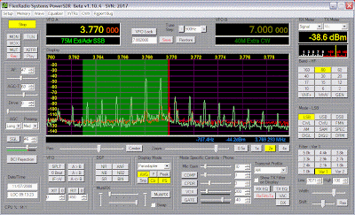
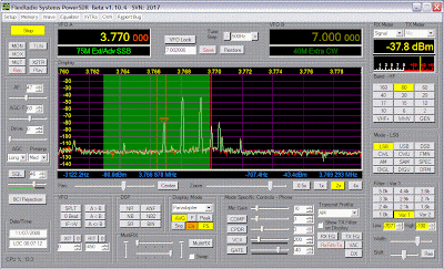
For example, here are two different IMD plots:

(You can enlarge either image by clicking on it.) 


The first plot is my Flex 5000 at 0.1 watts. The second is the same transmitter at 100 watts. 

Note how, in both plots, the third-order products are essentially at the same level relative to the two-tone test tones. 

Yet, these two transmitters sound different. 

The difference is subtle, yet it's there. And if you look at the images, it's obvious why there's a difference: it's because, at 100 watts, the higher-order distortion products are present, too. 
Sunday, July 6, 2008

Flex 5000 Driver Distortion vs. Final Distortion

Here's another test of TRANSMIT Audio. To listen to it, send an email to jca1955 "at" sbcglobal.net and ask for the 6 July 08 test file, and I'll send you the mp3 file.

This mp3 again contains two recordings, but this time the source of both recordings is the same 5K (and again, feeding into a second SDR-1K as RF-demodulator/recorder). One recording was made by demodulating the RF received from the 5K's output antenna connector (in other words, the output from the 5K's PA), while the other recording was made by demodulating the RF tapped from the coupling transformer between the Driver and Final stages of the 5k's PA.

In both cases, the 5K was operated at full power (100 watts) and fed into a dummy load. I sampled the Final output by attaching an RF "tap" (essentially a 100:1 voltage divider) between the 5K's antenna connector and my external dummy load. The tap's output was then fed to my "receive" SDR-1K via a big attenuator.

To sample the signal from the 5K's Driver stage (to the Final stage input), I added a single turn link to the transformer between these two stages which I then connected to a BNC. I then disconnected the coax that had been connected to the RF tap (the other end goes to the 1K) and connected it instead to this new BNC at the Driver output. I kept the same big attenuator that I had attached at the input to the 1K receiver. In this configuration signal levels (at the 1K) are essentially equivalent for both configurations when measured with the 5K in TUNE mode.

Again, I used my Heil PR-40 mic as the audio input, and I read the same phrase for each test. TX bandwidth was 100 - 5KHz.

The first recording is from the Driver stage output. The second is from the Final stage (i.e. taken from my external "RF tap" attached to the 5K antenna output). Notice how the Driver stage sounds clean and the output from the PA stage sounds worse? This points to the PA stage (the final two FETs) as being the main source of my Flex 5000 transmit distortion.

Saturday, July 5, 2008

Another recording of Flex TX audio...

[Unfortunately, the file cannot be directly downloaded from the web. Instead, please send an email to jca1955 "at" sbcglobal.net and ask me for the 5 July 08 Audio test file, and I'll send you the mp3.]

The radios are in the same order as the 1 July test, but this time I used the mic input (and my Heil PR-40) in lieu of a WAV file as my input source.

Each radio was terminated with a dummy load connected to the antenna terminal.

Thursday, July 3, 2008

Flex TX Audio...

I've made an MP3 containing two recordings. One recording is the TX audio from my SDR 1000, the other is the TX audio from my Flex 5000. To obtain this recording, send an email to jca1955 "at" sbcglobal.net and request the Flex 1 July 08 Audio test file. I'll send you the mp3.

Once you've received this file, take a listen. What do you think - is there a difference between the two? If so, which sounds better (first or second recording), and why?

The recordings were made using the same WAV file as the audio source for the transmitters (using the playback feature of the Flex Console WAVE tab), so this test is really just testing each radio's output from DAC through the TX mixer and the Driver and Final stages.

I used a second SDR 1000 to receive the RF from each of the two radios "under test" (by connecting each test radio's output to the input of my second 1000 via a BIG attenuator), and I made the recordings using this second radio (again, using the WAVE tab of the Flex Console - this time in Record mode).

TX setups were the same for the 1K and the 5K (EQ, etc.). TX Bandwidth was 100 Hz - 5 KHz.

Receive bandwidth (on the second flex 1000) was 100 Hz - 5 KHz. No RX EQ.

By the way...if you listen to the recordings, please do so before reading the comments (so that you're not prejudiced one way or the other). And I haven't identified which audio is from the 1K and which is from the 5K, because, again, I don't want to prejudice any views beforehand.

Thanks!