The November, 2023 issue of QST has an interesting antenna article titled, "The LPi Antenna," which describes a broadband antenna covering 21-29.7 MHz with an SWR of less than 3:1.
Given its asymmetrical shape and its high feed-point impedance, the LPi antenna is fed via both a common-mode choke (to reduce common-mode currents that might be introduced due to antenna asymmetry) and an unun configured to be a 4:1 impedance transformer (to transform a high load impedance to a lower impedance, e.g. a 200 ohm load impedance to 50 ohms).
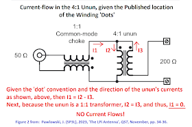
A schematic representing these two transformers is shown in Figure 2 of the article:
As drawn in the article's Figure 2, this circuit cannot work because both of the 'dotted' terminals of the 4:1 unun are driven by the same signal.
Clearly this effect was not the intent of the author and thus the schematic was incorrectly drawn. (Note: although no current will flow in an ideal unun if its two dotted terminals are connected together, in fact the unun is not an ideal transformer, so some current will flow through it even if both dotted terminals are tied together, but in this case the device will appear to be a series impedance and not an impedance transformer.)
What should be the correct schematic?
First, let's look at how the transformer dot convention defines the directions of a transformer's current. Per the dot convention, and given a two-winding transformer, if current is flowing 'into' the dotted terminal of Port 1, then it will flow 'out of' the dotted terminal of Port 2.
Given this convention, if both dotted terminals were tied together and driven in common, no current would flow through the transformer windings. We can show this result algebraically, in the figure, below:
What is the correct schematic for the choke/unun circuit? The dotted terminals for the two windings should be at opposite ends of the unun transformer, as shown in the diagram, below:
To verify that this is schematic is correct, we can compare it to the actual wiring of the choke/unun pair as shown in Figure 3 of the QST article.
To identify each transformer's "dotted" terminals, note that because both the common-mode choke and the unun are wound with coax, both the shield and the center-conductor at one end of the length of coax used for a transformer's windings can be considered to be its two dotted terminals. In the image, below, I've added two dots to one end of the common-mode choke's coax winding (one dot next to the center-conductor and one dot next to the shield) and also two dots to one end of the unun's coax winding.
If you examine the connections of the 'dotted' shields and center-conductors of these two coax cables in the image, above, you will see that they match the wiring in my 'corrected' schematic of the choke plus unun circuit.
Alternative Representations of the Corrected Schematic:
Per the comment from KE5FX (see comments section), I thought it would be useful to add a couple of alternative ways to draw the same corrected schematic. Note that I'm using the "dotted" transformer terminals as they were shown in the original article; I'm just changing how the unun is wired.
If we redraw the circuit above, we can see that the unun is actually a center-tapped auto-transformer, as shown, below:
These two representations are both functionally equivalent to my corrected schematic earlier in this blog post.
Standard Caveat:
As always, I might have made a mistake in my equations, assumptions, drawings, or interpretations. If you see anything you believe to be in error or if anything is confusing, please feel free to contact me or comment below.
And so I should add -- this information is distributed in the hope that it will be useful, but WITHOUT ANY WARRANTY; without even the implied warranty of MERCHANTABILITY or FITNESS FOR A PARTICULAR PURPOSE.


