|
(Radio Shack SWR/Field-Strength Meter, purchased circa 1970 when I was a
young Novice (original 100uA meter replaced with generic meter during
the early 1970s))
|
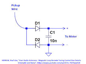
A friend of mine who was building a field-strength meter as a tuning-aid for
his magnetic-loop antenna asked my opinion of the following schematic:
I took a quick look at it and told him that I thought that diode D2 was not
needed (thinking that if D1 charged up C1, then D2 would have no role in the
determining C1's voltage -- after all, if D2 were conducting, then D1 would be
back-biased and C1's voltage would remain unchanged).
Well, I was wrong.
My friend built the field-strength meter and quickly determined that the
second diode was needed. Without it, the meter would always read
zero.
Why was the second diode required? Clearly, I needed to take a closer
look...
Creating a Model for Analysis:
Field-strength meters, given that they use a whip antenna, can be thought of
as an electric-field (E-field) detector, rather than a magnetic field
detector.
When used, the typical field-strength meter might be sitting on a table-top or
mounted on a wall or even hand-held. That is, they are often not
directly connected to ground:
What is the signal path between the transmitter and the field-strength meter
when the field-strength meter is not directly connected to ground?
The image below shows a path that is not the signal path, given
a meter being used as an E-field detector. (It would be a valid
path if the circuit were used as a magnetic field probe, but in such an
application the whip antenna would not be needed and you could replace one
diode with a short).
Continuing with the field-strength meter as an E-field detector analogy, for
purposes of analysis we can picture the field-strength meter as being
capacitively coupled (E-field coupled) to the transmitter and to ground via the
three paths shown in the image, below:
And again, for purposes of analysis, let's assume that one of the two legs
capacitively coupling the meter's terminals to ground has more capacitance
than the other leg, so that it dominates.
Note: It doesn't matter which leg dominates, the meter works in either
case (as can be shown with LTSpice simulations). In fact, it also works
if the capacitances of the two legs are equal.
But for simplicity, let's treat the meter as having the following two
capacitively coupled paths:
Because the two capacitors in the signal path (antenna to antenna, meter to
ground) are in series with the field-strength meter, for analysis purposes I
can combine these two series-capacitors into an equivalent single capacitor. Also, for
simulation I'll remove the capacitor across the meter and replace the meter
with a resistor. Thus, any current flowing through diode D2 also flows
through the resistor.
Here's the LTSpice circuit:
The driving signal is a sinusoidal voltage at 10 MHz. The image below
shows the simulation results.
You can see that the voltage across the resistor R1 (i.e. through the meter)
is a pulsating positive DC voltage. Therefore, the meter would
deflect from 0 by an amount related to the RMS level of this pulsating
waveform.
Note, too, that current flows through C3 during the entire cycle of the
sinusoidal source.
The simulation below is of the same circuit, but it shows the voltage across
the capacitor C3 as well as the diode-clamping effect at node B:
And for completeness, below are two simulations. The first has the capacitance in the other
leg dominate and the second has both "leg" capacitances equal:
Note that for the "equal leg" simulation the voltage across R1 looks more
like a full-wave rectifier's output.
Circuit with One Diode:
But what happens if I remove a diode?
Below is the LTSPICE circuit (with the two series-capacitors in the loop
combined into one):
And here is its simulation:
Note that with the first positive transition of the driving source's
sine-wave, capacitor C3 charges up to a value essentially equal to V1(pk) -
Vf(diode) (assuming that the voltage drop across R1 is much smaller than
Vf(diode).
During the positive portion of the source's cycle, the circuit's loop
equation is:
V1 -VC3 - Vdiode - VR1 = 0
Or,
VR1 = V1 - VC3 - Vdiode
Given that VC3 = V1(pk) - Vf(diode), then the diode is never be forward
biased into conduction during the sine wave's positive cycle and thus no
current would flow through the meter.
During the negative portion of the source's cycle, the diode is always
back-biased. Thus no current flows and the meter never deflects.
And so, if the circuit only has one diode, no current flows through the
meter (apart from the initial transient) and its reading is always zero.
(Note: as a general design rule this means that, when capacitively
coupling a diode-detector to a voltage source, you should use two diodes
and not one).
Other comments:
If the capacitors are large enough that their impedances are low at the
frequency of operation, then the circuit is similar to that of a classic
voltage doubler.
Here's a classic voltage doubler:
And here's the FSM with its "implied" capacitive couplings set to large values
of capacitance:

Standard Caveat:
I might have made a mistake in my designs, equations,
schematics, models, etc. If anything looks confusing or wrong to you,
please feel free to comment below or send me an email.
Also, I
will note:
This design and any associated information is
distributed in the hope that it will be useful, but WITHOUT ANY WARRANTY;
without even the implied warranty of MERCHANTABILITY or FITNESS FOR A
PARTICULAR PURPOSE.


No comments:
Post a Comment