This switch is an elastomeric push-button switch, in which a small conductive disk on the backside of the rubber pushbutton "shorts" two contacts on the switch PCB when the pushbutton is pressed.
Chances are that the PCB switch contacts needed to be cleaned, but to do this the Front Panel Assembly must be removed from the 6060B chassis and then disassembled to access the push-button's circuit-board pads. Section 4B-4 of the Fluke 6060B manual describes a procedure for removing the Front Panel Assembly, but this procedure is incomplete.
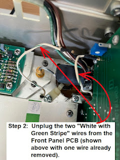
Below are the steps required to remove the Front Panel Assembly from the chassis and then disassemble it so that the pushbutton switch contacts can be cleaned:
Removing the Front Panel Assembly:
If there is physical interference between the edge of the PCB and the metal bracket, as shown above, consider filing a small notch in the PCB to allow it to clear the bracket.
Cleaning the PCB's Switch Contacts:
The switch contacts on the PCB can be cleaned with either Isopropyl Alcohol (I used a 99% solution). They can also be cleaned with distilled water. In either case, wet the tip of a Q-tip with your preferred solution and gently wipe away any loose residue on the PCB's switch pads. Use a clean Q-tip to dry the pads.
I would also recommend a gentle cleaning of the conductive disk that is attached to the rubber push-button (it is this disk that completes the switch contact when the pushbutton is pressed).
To test the resistance of the RF Output On/Off switch when it is depressed, place an ohm-meter across the two PCB vias shown in the image, below, and press the switch. After cleaning, I measured about 1.5K Ohms when the switch was pressed). Other switches measured in the range of 500 to 1200 ohms. Note that this resistance seems to be the resistance across the small conductive "pad" on the back of the rubber elastomeric switch.
Reassembly:
To reassemble, perform steps 1 through 9 in reverse order!
A Tip:
Keep the screws for each step in separate cups. This will make reassembly much easier.
Standard Caveat:
As always, I might have made a mistake in my equations, assumptions, drawings, or interpretations. If you see anything you believe to be in error or if anything is confusing, please feel free to contact me or comment below.
And so I should add -- this information is distributed in the hope that it will be useful, but WITHOUT ANY WARRANTY; without even the implied warranty of MERCHANTABILITY or FITNESS FOR A PARTICULAR PURPOSE.


No comments:
Post a Comment