In Part 1 I evaluated a Class E/F amplifier using a center-tapped transformer
to supply power to the drains of the two active devices.
DC power can also be fed to the drains of the two MOSFETs via two inductors,
thus simplifying the transformer because it no longer needs to be
center-tapped. I was curious how such a circuit compared (in performance) to
the circuit described in Part 1.
Here's the SPICE model (using Linear Technology's free SPICE program:
LTSpice):
Regarding the model:
1. C4, at 1 Farad, provides a "stiff" AC ground for simulation purposes so
that there's no voltage fluctuation at the R4, C4, L1, L2 node.
2. L1 and L2 provide a high-impedance feed for DC power to the "Drains" of the
MOSFETs. I chose these to be (initially) 25 uH.
3. The MOSFETs are modeled with voltage-controlled switches. Their Ron is set
via external resistors to be 0.15 Ω (plus 0.01 Ω within the Switch
model).
4. 500 pf capacitors mimic the MOSFETs' Coss (per the IRF 530
datasheet). Note that these capacitors are
not voltage dependent.
5. Refer to
Part 1
for more detail on selecting the Transformer inductance of 400 nH.
6. C3 was arrived at by trial-and-error (after initially setting its value to
3.655 nF per
Part 1) by adjusting its value so that the voltage waveform at node "Va" is zero
when the current waveform (through R1) is non-zero.
When adjust the value of C3 (or the transformer's inductance), the current and
voltage waveforms maintain the same relationship to C3's value (or to the
transformer's inductance) as was described in
Part 1. Refer to the image below.
Lowering RMS current through the switches:
I thought I'd see if I could lower power dissipation in the switching devices
by lowering their RMS current (see
Part 1
for more discussion on this technique). By lowering the value of inductance of
L1 and L2, I could replicate current waveforms through the switching devices
that look as though the amplifier is now a a "Class E/F2,odd" amplifier, but, when I made my measurements using the tools in LTSpice,
there was really only minimal effect (if any) in power dissipation.
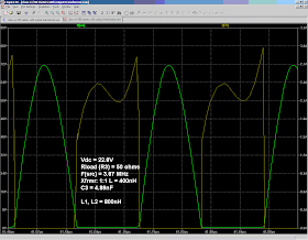
Here's how the waveforms look with L1 and L2 reduced to 800 nH. As the table
following this image shows, although the current-waveform changes
significantly, there isn't much of a difference in switching-device
power-dissipation (as measured across R1 and R2).
I used the LTSpice measurement functions to measure power and RMS current at
different points in the circuit (for various values of L1, L2), and these
measurements have been tabulated below.
Some observations from this table:
- I really cannot see much change in R1's power dissipation as L1, L2 are varied. That is, the differences are small, and perhaps are within the tolerance of simulation errors.
- Also, there's not much change in either Output Power (Pload) or efficiency for the range of values of L1 and L2 shown in the table. Therefore, a L1, L2 values in the range of, say, 25 uH - 100 uH, might be the simplest approach for my application.
- As L1, L2 are decreased, C3 must be increased to compensate for their effect on the time-relationship of the voltage and current waveforms. However, an increase in the value of C3 increases the current through C3 (because voltage across the transformer is essentially constant, and we decrease C3's reactive impedance when we increase its value). Therefore, due to its internal ESR, C3 will dissipate more power when L1,L2 are reduced.
- As the values of L1 and L2 is increased, it takes longer for the simulation waveforms to ramp up to their final values.
It's possible, though, that in applications in which higher currents are
present, some benefit might be achieved by "tuning" L1 and L2. However, the
simulations don't bear this out in my application, and there seems to be
little benefit.
Overall, the power-out from this circuit topology is comparable to that of the
center-tapped transformer topology described in
Part 1. So, for my application, either circuit should do the job, and it'll just be
a matter of determining which one is easiest to build.
Modeling with the IRF530 MOSFET
Actual MOSFETs can be simulated via LTSpice's "nmos" model, within which one
can retrieve the SPICE parameters for a number of different MOSFETs, including
the IRF530. (Note: these devices are
not alphabetized in the "Pick New
MOSFET" table.)
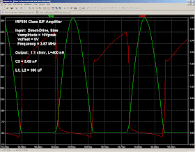
Below is a circuit with IRF530 MOSFETs substituting for the original
voltage-controlled switches. The final value of C3, as well as the AC source's
amplitude and offset voltage (V2), were arrived at by trial-and-error. Also,
two AC sources are used (the second with an offset of 180 degrees), because it
seemed like an easy way to provide two sine-wave sources that were 180 degrees
out of phase but with the same DC offset.
(Click on image to enlarge)
- The Sine Wave sources have an amplitude of 10 Vpeak and a DC offset of 5V (to bias the IRF530's near their turn-on point). This gives peak gate voltages of +15/-5 Volts (note that the max rating of the IRF530's gate voltage (VGS) is +/- 20V).
- C3 is now 3.69 nF.
Note: Source current is shown, rather
than Drain current, because the Drain
pin has quite a bit of current flowing through it even when the MOSFET is OFF.
This current at the Drain pin is not dissipative current, though (that is, it
isn't being dissipated as I2 * R heat through RDS(on).
Instead, it's current
passing through the
Gate-Drain capacitance and out the
Gate pin (LTSpice plots verify that I(drain) - I(gate) = I(source)).
Here are some of the currents and powers (and overall efficiency) measured via
LTSpice.
- RF Power Out: 48.2 watts
- DC Power In: 52.0 watts
- Efficiency: η = 48.2/52.0 = 93%
- IL1 = 1.14 ARMS
- IC3 = 4.5 ARMS
- IL3 = 5.2 ARMS
References:
Spice:
Class E Amplifiers:
Caveats:
- Sokal, "Class-E RF Power Amplifier", Jan/Feb 2001, QEX
- Sokal, "Class-E High-Efficiency RF/Microwave Amplifiers", (a more detailed paper)
- Lau, Chiu, Qin, Davis, Potter, Rutledge, "High-Efficiency Class-E Power Amplifiers" Part 1, May '97, QST, and Part 2, June '97 QST
- Davis, Rutledge,"A Low-Cost Class-E Amplifier with Sine-Wave Drive"
- Der-Stepanians, Rutledge, "10-MHz Class-E PowerAmplifiers"
- Melia, Robert, O'Conner, Class-E Power Amplifier Design
- Tayloe, Class E Amplifiers (Norcal QRP Presentation)
- Class E Design Software from Tonne Software (I've never used this, so use at your own risk)
- WA0ITP Class-E Amplifier Design Spreadsheet (I've never used this, so use at your own risk)
- Class-E AM Forum
- Class-E AM Transmitters (WA1QIX)
- Class-E Amplifier Experiments , Calculations, and Notes on Designing Class-E RF Amplifiers, all by Bill Slade. (I've not verified the accuracy of these posts.)
- Taniguchi, Potter, Rutledge, "A 200 W Power Amplifier", Jan/Feb 2004, QEX
- Letters, May/June 2004, QEX
- Letters, July/August 2004, QEX
- Kee, Aoki, Hajimiri, Rutledge, "The Class E/F Family of ZVS Amplifiers"
- Kee, "The Class E/F family of Harmonic-Tuned Switching Power Amplifiers" (Cal Tech Thesis)
- Kee, Aoki, Rutledge, "7.1 MHz, 1.1 KW Demonstration of the New E/F2,odd Switching Amplifier Class"
- Jeon, "Design and Stability Analysis Techniques for Switching Mode Non-Linear Circuits: Power Amplifiers and Oscillators" (Cal Tech Thesis)
- Kee, et al. U.S. Patent, No. 6,724,255
- Niknejad, "Class E/F Amplifiers" (presentation, EECS 242, U.C. Berkeley)
- Bohn, Kee, Hajimiri "Demonstration of a Switchless Class E/Fodd Dual-Band Power Amplifier (a 40 and 30 meter dual-band amp)
1. These simulations are for educational purposes only.
2. I could have easily have made a mistake, so please view (and use) these
simulations accordingly.
3. And a final caveat regarding SPICE modeling. Modeling results should always
be taken with a bit of caution, for the ability of SPICE to mimic actual
circuit behavior depends in large part on how accurately a circuit and its
components have been modeled. Factors such as parasitic components and circuit
non-linearities can all cause modeled SPICE performance to diverge from
actual performance. SPICE can provide
valuable insights into circuit operation, but a bit of skepticism, too, should
be applied when evaluating results.


Great blog!
ReplyDeleteI stumbled across it looking for "Heatkit Paint", and wound up spending quite a bit of time here.
73, Jim KQ6EA
Very good blog. Thanks for shareing all this info. I want to build a class e amp to attack a coil antenna. Will the coil antenna affect the frequency of the amplifier? The impedance my load (the coil actualy) is not only real, is it ok? How do I do that?
ReplyDeletethanks.
If the antenna's impedance is reactive, it will affect the load seen by the PA devices. You either need to cancel out that reactance externally, or absorb it into the PA's output network (which is somewhat reactive, anyway, to give the appropriate Voltage versus Current waveforms).
ReplyDeleteUnfortunately, as far as I know, switched topologies (class D, E, F) are NOT linear. They are good for continuos wave (CW at full power) or PWM/PCM amplification 8as in digital audio), but not for AM based linear modulations (AM, SSB). They should require Vdd modulation to be linear otherwise they cannot amplify AM/SSB properly.
ReplyDeleteDear IZ2DQB:
ReplyDeleteTo be more specific, output voltage needs to vary linearly for SSB or AM modulation when using a Class E amplifier. But note that this can be accomplished without modulating Vdd.
There is an interesting transceiver (the uSDX) that creates SSB signals completely digitally and uses a Class E PA. Rather than modulating the PA's Vdd, the design varies the PA's output voltage amplitude by pulse-width modulating the on/off digital signal driving the PA transistor's input.
To quote from the uSDX GitHub Site (https://github.com/threeme3/usdx):
"The SSB transmit-stage is implemented entirely in digital and software-based manner: at the heart the ATMEGA328P is sampling the input-audio and reconstructing a SSB-signal by controlling the SI5351 PLL phase (through tiny frequency changes over 800kbit/s I2C) and controlling the PA Power (through PWM on the key-shaping circuit). In this way a highly power-efficient class-E driven SSB-signal can be realized."
It is an interesting design (and modulation technique) using remarkably few parts. Of course, this technique is very DSP intensive!
Best regards,
- Jeff, k6jca