When doing these sorts of analyses, I usually also want to know how the circuit performs at temperature extremes to ensure that, given the temperature characteristics of semiconductor junctions, the circuit's performance is still acceptable. So, while analyzing the circuit for worst-case component variations, I can simultaneously use the SPICE .step command to step the temperature (in degrees Celsius) over the range I'm interested in.
Here's a simple circuit demonstrating this:
(click on image to enlarge)
This is a comparator circuit in which the reference voltage is set by a zener diode, D1. I'd like to know how this circuit performs at the temperature extremes of -55 and +125 degrees C, as well as how it performs for the worst-case resistor values, given their tolerance of 1%. So there are two .step commands: one to vary temperature and one to vary resistor values.
Because I'm only interested in the two temperature extremes and not in any intermediary temperatures, I'm going to define the temperature to step from -55 degrees to +125 degrees in a single step of 180 degrees. The command is:
.step temp -55 125 180
(Note that if I wanted to step the temperature between these two limits in, say, 10 degree increments, the command would be: .step temp -55 125 10).
The second .step command defines that there will be 50 runs, for each of which the values of the resistors will be randomly varied between their worst-case values (as defined by their tolerances).
So we have two .step commands, one which will vary temperature between 2 values, and the other which will perform 50 worst-case runs. Spice nests the step commands, so, overall, there will be a total of 100 runs performed (2 temp runs for each of the 50 worst-case runs).
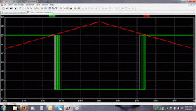
This circuit has hysteresis (via R7), but what effect will it have on the switching threshold, given that a zener is used for the reference voltage? I'll define the input voltage source V1 to linearly ramp up from 9 to 15V and then to ramp back down to 9V over a 1 second period (there may be a simpler way of doing this with SPICE, but this method works, too), to check performance during low-to-high and high-to-low transitions.
Below are the plots from the 80 runs, showing how the comparator threshold changes due to component tolerances and temperature variations (component tolerance, even though 1%, results in the greatest variation in performance). The left half of the plot shows the comparator threshold as the input voltage increases from low to high, and the right half shows it as the input voltage decreases from high to low.
(click on image to enlarge)
Here's a plot showing how the voltage at the node "V+" (the node attached to the zener diode) changes between the two temperature extremes (there's about a 50 mV delta):
(click on image to enlarge)
Additional Notes
1. As mentioned, this circuit has two step sweeps: one for temp and one for run (in which the resistor values are varied for worst-case analysis). Note that LTSpice allows step sweeps to be nested up to three deep.
2. LTSpice is available, for free, from Linear Technology, and can be found here.


Hi,
ReplyDeleteGood post!
I was wondering, do you know a way to to set the Monte-Carlo tolerance to the Zener diode?
Thanks