Introduction:
This blog post is a continuation of my two earlier GPSDO blog
posts. The first one (from a few years back) details a simple Frequency-Locked Loop GPSDO
design, based around an Arduino processor. The second (more recent) blog post discusses simulating Brooks Shera's GPSDO
algorithm (from the July, 1998 issue of QST) using The MathWorks
Simulink program.

This third blog posts describes my modification of my original
Frequency-Locked Loop (FLL) GPSDO to be a Phase-Locked Loop (PLL) GPSDO, and
it includes the hardware schematics, Simulink models, and the Arduino code I
wrote to implement Brooks Shera's GSPDO algorithm on an Arduino processor.
My
notes are here to organize them in one place (and not have them scattered
across different folders, notebooks, and loose sheets of paper), and also so
that others who want to construct or experiment with their own GPSDO designs
might find my notes useful in furthering their own projects.
You
should be able to find a copy of Brooks Shera's original July
1998, QST article at either the ARRL website or here:
https://www.qsl.net/n9zia/wireless/QST_GPS.pdf

Simulink Simulation Model:
System modeling can be a huge design time-saver, as it allows one
to experiment with various circuit topologies and algorithms before writing
actual code or designing actual hardware.
In my specific case, I
first created a "Phase-Space" Simulink model of Shera's algorithm and hardware
from his original QST article.

This model allows me to vary parameters and see how, for example, the
VCO (and DAC input/output) respond to various "reference" (1 PPS) signal
perturbations. (For more information on this Shera Simulink model, go
here: http://k6jca.blogspot.com/2018/12/simulating-brooks-shera-w5ojm-gpsdo.html -- note, this Simulink model is for a 10 MHz VCO, but I also show the
VCO response for a 5 MHz VCO (per Shera's original design) in the blog
post)).
To investigate how I could adapt my Arduino hardware and
code to match the Shera design, I then created a new Phase-Space Simulink
model incorporating Shera's algorithm but modified for my particular FLL GPSDO
hardware platform:

Using the same stimulus to drive both models simultaneously, I can then compare the responses of this new model to the responses created by Shera's original model:

Arduino/Shera Simulink Model:
Let's look more
closely at my Arduino/Shera Simulink model. In many respects it is
similar to my model of Shera's original design, but there are differences that
arise due to differences in my Arduino hardware compared to Brooks'
design. (I would recommend first familiarizing oneself with the Brooks
Shera Simulink model at this blog post: http://k6jca.blogspot.com/2018/12/simulating-brooks-shera-w5ojm-gpsdo.html.)
Here, again, is the Arduino/Shera model:

Note that the different color traces and blocks refer to their time
domains, as defined below:

For the most part the model should be self-explanatory. But there
are some subsystem blocks that we should click on to see what is going on
inside them...
First, the phase-wrapper block. This block is
instantiated as a MATLAB function:

Next, here's the FIR "boxcar" filter that sums together (with equal
weighting) 30 samples.

And here is the down-sampler that samples the FIR "boxcar" filter's
output once every 30 samples:

Now let's look at the heart of Shera's algorithm, his IIR
(Infinite-Impulse-Response) filtering...
Below is the IIR block as
it is shown in the Simulink model's top-level. If you compare the
constants (in purple) with the model of Shera's original design, you will note
that they are different. I will explain why, later in this post.

If we click on the "Shera Software IIR Loop Compensator" block, we see
the model for the IIR filter, itself:

If we return to the model's top-level and then click on the subsystem
block representing the 16-bit DAC, we will see the following:

Note that the DAC's output goes from 0 to +5 for unsigned inputs from 0
to 65535.
Also, this subsystem has two outputs -- the lower output
represents the DAC's voltage output, while the upper output is used solely for
displaying (via Simulink) the DAC's output as a signed value.
There
is an input function that "clips" the incoming value, which mimics what I do
in the Arduino software when calculating values to send to the DAC.
If
we return back to the model's top level and then click on the VCO subsystem
block, we see the VCO model:

Note that the VCO itself is simply represented by the 1/s integrator
(phase is the integral of frequency).
Functionally, my
Arduino/Shera hardware differs from Shera's original as follows:
- My phase detector, over 30 seconds, should have a maximum possible value of 24660 (i.e. 30*822). Shera's phase detector has a maximum possible value of 2304 (i.e 30*76.8) for the same 30 second period of phase delta integration.
- My DAC is 16 bits unsigned, with a 5 volt output range. Shera's design uses an 18 bit signed DAC, with a 6 volt output range (-3 to +3 volts).
- My Arduino hardware creates a -5 to +5 voltage from the DAC output (i.e. a gain of 2 with a DC offset -- this circuit is from my original FLL design, and I did not want to remove it). Shera's design does not amplify his DAC output.
- My VCO's Kv is -0.32 Hz/V. Shera's design assumes a VCO Kv of 0.075 Hz/V at 10 MHz.
- My design divides the VCO's output (to the phase detector) by 8 to create 1.25 MHz. Shera's designed divides the VCO by 32 (if the VCO frequency is 10 MHz) to create 312.5 KHz.
In the model subsection below, the gray block represents the voltage-gain of
+2 (plus DC offset) that exists in my hardware (implemented with two op-amps)
to amplify and DC-shift the 16-bit DAC's output.
The yellow block
contains the different compensations (implemented in hardware) that I use to
compensate for each of the hardware differences that I have listed above.

Following the signal path in the yellow block, these compensations
are:
- Compensate for my hardware's external op-amp gain of two by multiplying by 0.5.
- (Next, a "catch-all" attenuation (for experimentation), labeled ExtAtten).
- Compensate for my DAC's 5V range (compared to Shera's 6 volt range) by multiplying by 6/5.
- Compensate for my N value of 8 (i.e. VCO divider) compared to Shera's N value of 32 (for the Shera design if using a 10 MHz VCO in lieu of his original 5 MHz VCO).
- Compensation for my different value of VCO Kv. (Shera's design assumes a Kv of 0.075 Hz/V -- see discussion regarding Shera's "S" factor in the "Other Notes and Thoughts" section at the end of this blog post).
- (Note that the compensation for the difference in phase-detector max values is done in software. Refer to the model's top-level and you will see that the filter output (either IIR or Type 1 filter) is multiplied by the ratio of 2304/24660 prior to sending this value to the DAC input.)
As I mentioned above, these gain-compensations in the yellow block are
all external to the software. That is, they are
combined and implemented between the DAC output and the VCO's EFC input as a
resistive voltage-divider.
If we take into account all of the
compensations listed above, this attenuator should attenuate the EFC signal to
the VCO by a factor of 0.035 (i.e. 1/28 or 1/29). Note that more
attenuation (which decreases the overall loop gain), either in software or in
hardware, will increase ringing on the VCO response
and decrease its rise time to a step at the phase detector
input.
By the way, any of these hardware compensations could be
implemented, instead, in software. I chose not to, because implementing
these attenuations in software (prior to the DAC) would reduce the DAC's input
with respect to its Full Scale value (after all, they are attenuations and not
gains), and I wanted to retain the same DAC input values that the original
Shera design uses.
Finally, let's look at the Simulations'
input stimulus section...

There are two different stimuli available for testing. One
stimulus is a step-function (whose amplitude has been set to 400
nanoseconds):

And the second stimulus is an Excel file containing actual 1 PPS jitter
data. In the above example, this data is from a Trimble Resolution T GPS
receiver, but there is also an Excel file with data from the Quectel L76 GPS
receiver. (Refer to this blog post for more info: http://k6jca.blogspot.com/2018/12/simulating-brooks-shera-w5ojm-gpsdo.html)
The stimulus data (for whichever stimulus is selected) is then
normalized to the appropriate phase-detector's period. E.g. the stimulus
for the Arduino phase detector is normalized to 800 ns, and thus, for the 400
nanosecond step function, its value should be 0.5 after normalization.
Similarly,
the stimulus is normalized for the original Shera phase detector's
period. In this case, this period is 3200 ns, so a 400 nanosecond step
normalizes to 0.125.
The normalized step function is then added to
0.5. This 0.5 represents a phase that equals the setpoint, when
normalized, so it should represent an ideal phase-delta error of 0 (i.e. when
the setpoint is subtracted from the phase-delta). In other words, at
startup, the model starts with no phase perturbations and in lock.
Let's
now look at simulation results...
Simulation Results:
These simulations all use the 400 nanosecond step-function stimulus.
Type 1 Filter Responses:
First, let's look at how the Type 1 filter responds to this step
function.
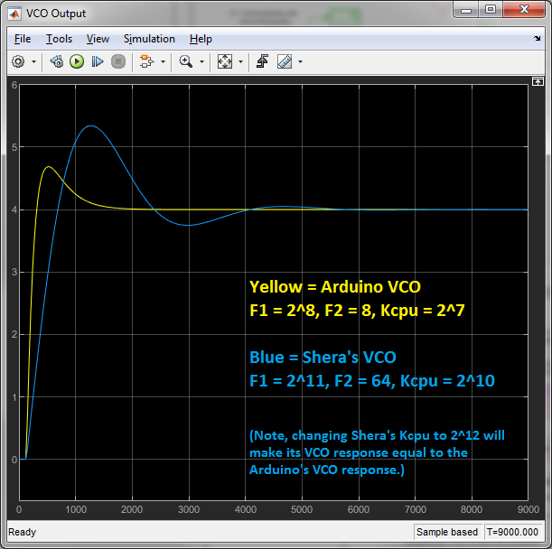
Here's a plot of the responses for both the Arduino and
the original Shera VCOs:

Note that these two responses are exactly the same.
And here
is the DAC inputs for both models:

Again, the DAC inputs are exactly the same.
Note that, if I
were exactly matching Arduino to original Shera, then the DAC input values of
each design should have the same relation with respect to the DAC full-scale
value. For example, given the same stimulus driving both models, if the
peak value in Shera's DAC were, say, 1/5 of DAC full scale value, then the
peak value at my DAC's input should also be 1/5 of that DAC's full scale
value.
Given that the Shera DAC is 18 bits and my DAC is 16 bits,
then, to maintain the same "ratio-to-full-scale," my input values should be
reduced by a factor of 4.
But dividing the 16-bit DAC's input by
four essentially reduces its resolution. Given that, for a positive 400
ns phase step, the 16-bit DAC's peak input is only about 9000 compared to a
maximum positive input for this DAC of 32767, I decided I had plenty of
headroom and that it would be a fairly safe gamble to make the input values to
the two DACs equal, rather than scaling my inputs down by a factor of 4.
IIR Filter Responses:
Here are the VCO responses for the first Shera IIR filter (this
is the filter selected when his filter select switch is set to '2'):

Again, the VCO responses for the two models are essentially
identical.
Similarly, the DAC input values for the two models are
also essentially identical.

Note that the maximum value is just less than 5000, implying that, for
the same step-input, DAC input range is determined by the Type 1 filter (which
had a larger transition at the DAC input), not the IIR filter.
The
plots above are for Shera's "lowest" filter. If we step sequentially
through the higher filters, we see that, for each step "up",
F1 increases by a factor of 2 and
Kcpu decreases by a factor of 2.
The net effect on
VCO response and peak DAC input (given the same step-function stimulus), is
that, for each step up to the next filter:
- VCO response rise-time and settling-time doubles.
- Peak DAC input is halved.
(You can see this effect in my Brooks Shera simulation blog post: http://k6jca.blogspot.com/2018/12/simulating-brooks-shera-w5ojm-gpsdo.html)
Simulation Experiments:
Now let's do some
experiments with our simulation model...
Experiment 1:
Increase Kcpu by a factor of 2 (i.e. double the overall loop gain):

Note that the rise time is a bit faster, but, compared to the original
Kcpu response (blue line) there is less overshoot and it settles more
quickly. (And note that the peak DAC input (for IIR filters) is,
essentially, doubled).
Experiment 2: Increase Kcpu by
a factor of 4:
The VCO response rises even more quickly, which might not be
desirable. And again, overshoot is lessened. And note that full
settling is at approximately 1500 seconds.
The peak DAC input is
essentially quadrupled, from the original 4.9K to 18K, which is starting to
get uncomfortably close (for me) to the maximum positive peak value of
32767.
Experiment 3: Let's take the last experiment
and "slow" the filter down by a factor of 2 (i.e. increase F1 by 2, from 2^8
to 2^9, and decrease Kcpu by 2, from 2^7 to 2^6, as we would do with Shera's
original filter constants):

Not too bad! The rise times are similar and the overshoot is
less. And the peak DAC input is about 9K, or twice the peak DAC input of
Shera's IIR Filter "2".
In my opinion, increasing the loop gain by
2, or by 4 (with a doubling of F1 for the latter) produces step-function VCO
responses that both seem, to me, to be better than the "stock" Shera filter's
step-response, as shown below.

Sidebar: A Mystery!
One point about my simulations puzzles me, and I haven't found a satisfactory explanation.
If you read Brooks Shera's article, he mentions that IIR filter 2 has a tau (time constant) of 1500 seconds.
As Shera notes, the time constant is "approximately the time required for the PLL to fully recover from a transient".
If you look at the plots for the lowest IIR filter (filter 2), it is close to complete recovery at abut 4000 seconds (although I might say it is fully recovered at 6000 seconds, which is four times the time constant specified by Shera).
Interestingly, increasing Kcpu by 2 seems to produce a settling time closer to 1500 seconds (i.e. 2000 seconds).
Why is there a difference? I don't know. I would almost believe that I've missed a gain of 2 or 4 somewhere in his hardware or software, but, if so, I cannot find it.
Oh well. A mystery!
Below is a table summarizing the results of the above experiments, plus
others, that I performed using the Simulink models:

IntAtten and ExtAtten are in the Simulink
model. The former is meant to be a software-only attenuation, prior to
the DAC, and the latter is meant to be a hardware-only attenuation, after the
DAC.
Note that the first four entries show how I progressed from
Shera's original values for F1, F2, and Kcpu (e.g. 2^11, 64, and 2^10,
respectively, for Filter 2, the minimum IIR filter) to the values I've used in
my Arduino model (F1 = 2^8, F2 = 8, Kcpu = 2^5). Note that they produce
the same VCO response (and DAC input) for the Arduino model that Shera's
original values produce for the "original Shera" Simulink model.
Regarding
the last table entry: these are values I would use if I changed the
phase-delta measurement period from 800 ns to 1600 ns (i.e. the period of 10
MHz / 16). Note that the external analog attenuation network
would not change. It would still be 1/28
(approx.). Because, although I've added a new attenuation of 0.5 (i.e.
ExtAtten), the attenuation compensation due to mismatched 'N' VCO-division
factors (between Arduino and Shera designs) decreases by a
factor of 2 with the new Arduino 'N' of 16. Thus, the increase in
ExtAtten is cancelled by the decrease in N-compensation attenuation.
Hardware:
The hardware is based upon my FLL hardware, with some small
changes to incorporate a Phase Detector and an EFC attenuator.
The
original FLL hardware is described in more detail in my original blog
post: http://k6jca.blogspot.com/2016/02/an-arduino-based-gps-disciplined.html. I would suggest first reading it if the functionality of the
circuitry below does not seem clear.
First, the main board with the
Arduino NANO subassembly.

There are only a few changes to this board from the description found in
this post: http://k6jca.blogspot.com/2016/02/an-arduino-based-gps-disciplined.html
These changes are:
- Change the serial port (J5) to be bidirectional, rather than TX-only to PC.
- Add the 10-pin header plug, P2, as the interface with the new PLL phase detector circuitry.
- Add 1-pin header J8 as an input pin for the 1PPS_3V3 signal (from the Quectel receiver via newly added 1-pin plug P3). J8 allows me to drive the Arduino with other 1 PPS sources (e.g. a Trimble Resolution T GPS receiver).
(Note: the earlier blog post, http://k6jca.blogspot.com/2016/02/an-arduino-based-gps-disciplined.html, also includes the modifications necessary to incorporate the Quectel GPS
receiver into the design.)
The following schematic is the
additional circuitry I added to incorporate a PLL phase detector into my
design.

Notes on the PLL Phase Detector circuitry:
- This circuitry attaches to the Arduino board via an 10-pin header (J4).
- The Quectel L76's 1 PPS output is spec'd with a VOL(max) = 0.42V and VOH(min) = 2.4V. This 1 PPS needs to go to an 'LVC74 flip flop operating at 5V. But the 'LVC74 VIH(min) is 3.5V -- significantly greater than Quectel's VOH(min). So U3, with its input specs of VIH(min) = 2V and VIL(max) = 0.8V, performs the signal-level translation from Quectel's 3.3V "1 PPS" signal to one with appropriate signal levels for the 'LVC74 operating at 5V.
- D flip-flops U1B, U6B, and U6A divide the 5 MHz clock (VCO clock divided by 2 on the Arduino board) by a factor of 8 to 1.25 MHz. (I originally started out with only a divide-by-two to create 2.5 MHz, but I discovered that its 400 ns period was too short to handle, for example, thermal drift when the Shera IIR filter is set to long time constants. So I added another 'LVC74 package to give me an additional divide-by-two, with a spare D flip-flop in case 800 ns should prove insufficient. So -- if starting from scratch, one could probably take all of this into account and use a different IC (or IC's) in lieu of my "growth by accretion" choices).
- Various jumpers are on the board solely for debugging purposes.
The D flip-flop U1A, in conjunction with the NAND gate U2 and the tri-state
buffer U4 (with its output RC network) are the heart of the phase
detector. Here's a closer look at its operation (shown in block diagram
form)...

More Phase Detector notes:
- The Tri-state buffer's output is enabled on the rising edge of the 1 PPS pulse, which starts the 1 nF capacitor charging through the 4K ohm resistor.
- The rising edge of the 1.25 MHz clock latches the logic state of the 1 PPS signal into the D flip-flop which, if the 1 PPS signal is high, sets the Q-not output low and puts the Tri-state buffer back into tri-state, stopping the charging of the 1 nF cap.
- Therefore, the 1 nF cap charges for the time period between the rising edge of the GPS 1 PPS pulse and the rising edge of the VCO 1.25 MHz clock. This period can range from 0 to 800 ns, depending upon the phase difference between these two edges.
- This capacitor connects to one of the Arduino's ADC inputs. The reference voltage for this ADC is 1.1V, and the values of the RC charging circuit (4K ohms and 1 nF) have been selected so that, if the phase difference between the clocks were 800 ns (the maximum amount), the capacitor would charge to about 4/5's of the ADC's full-scale value.
- The rising edge of the 1 PPS pulse also generates an interrupt at the Arduino (although, because there is an NPN inverter between the 1 PPS signal and the Arduino pin, this is a falling-edge interrupt), which initiates a read of the ADC. Note that it takes about 114 microseconds to complete the ADC read instruction, so there should be no danger of reading the ADC while the cap is charging (800 ns << 114 us).
- The 10 Meg ohm resistor (plus inherent leakage currents at U3's output and the Arduino ADC's input) discharge the capacitor during the remainder of the 1 second period, before the arrival of the next 1 PPS pulse.
- Note that the RC charging characteristic isn't a straight-line, it is an exponential curve. However, as I've shown in the graphs above, we are only using a small portion of this exponential curve (0 to about 0.9 volts in the graph), and for our purposes it is essentially linear.
- But, although "essentially" linear, it isn't exactly linear. I've shown the deviation from linear of this part of the exponential curve in the inset graph (plotting over 800 ns). The red line is the tangent to the exponential curve at T = 400 ns, which is the ideal spot that the PLL wants its Phase Delta to sit at (i.e. it's the Setpoint). Ideally, if the response were linear, we would move along this tangent line as we deviate away from the setpoint. But actually, as we move away from the setpoint, the actual voltage (along the exponential curve) deviates more and more from the ideal "linear" line. Fortunately, this deviation isn't much. In the ideal case, if the 1-second phase delta were to be at 300 ns or 500 ns (i.e. +/- 100 ns, or +/- 25% from the setpoint) then there is an error of about 0.4 %. Given the large amount of 1 PPS jitter, this error is, in my opinion, insignificant. (Note: this 0.4% is the ideal error -- it will change due to output stage non-linearities, etc.).
- The inset-graph above shows that the capacitor should charge to 0.9V over the full period of 800 ns. The ADC count for 0.9 V (given the ADC's 1.1V reference) should be 837 (=1023*0.9/1.1). The measured maximum ADC is 822. The difference between these two is most likely due to RC component tolerances and voltage drop across the output of the tri-state buffer.
By the way, the idea of a phase-detector using the charging of a capacitor and
reading its value via a processor's ADC is not a new one. Here are a
couple of links to similar designs (that inspired me to try the same
thing!): Lars GPSDO, and Kasper Pedersen GPSDO.
A few additional notes:
- For simplicity's sake I have not added any software temperature compensation.
- I used a tri-state gate to control the charging of C1 (similar to Pedersen's design) in lieu of a gate driving a diode (Lars design), because I believe the former, consisting of only one IC's output stage between +5VDC and the RC charging network, will have charging-voltage that is less sensitive to voltage variation with temperature, compared to the latter design, which consists of an IC's output stage in series with the temperature-sensitive Von drop of a diode. Note, though, that I haven't bothered to verify this belief.
The output reference-distribution schematic is unchanged from the
original FLL design:

There is a change to the power-supply / VCO Module interface
schematic. I have added a resistive attenuator to attenuate the VCO's
EFC voltage and a method for adjusting the EFC's offset.

The four resistors that perform this function (pots R1 and R4, resistors
R2 and R3) are very similar to Brooks Shera's design described in his
article.
Note: I implemented R1 with a 10 turn pot because I
wasn't sure how sensitive this adjustment might be in terms of "ohms per
turn" resolution.
R1 (in conjunction with R2 and the 5V from U10)
is used to set the VCO's frequency to be very close to 10 MHz when the DAC is
set to its midpoint (i.e. 0x8000). Note that this design only offsets
the EFC voltage in a positive direction, away from 0V.
R4 and R3
(in conjunction with R1 and R2) form external resistive divider that I
described above, in the Simulation model section. Note that if the
values of R1 (when adjusted) plus R2 are large with respect to R3 (100 ohms)
then R1 and R2 will have little impact on the value of R3 (the latter being
only 100 ohms), and the amount of attenuation can be approximated to be equal
to:
I used a 5K pot for R4, which gives me some flexibility in adjusting the
amount of attenuation.
Procedures for adjusting these pots are
described later in this blog post.
As an optional GPS
receiver in lieu of the Quectel L76 GPS receiver (per testing described later
in this post), here's a schematic incorporating a Trimble Resolution T GPS
receiver into my GPSDO design:

The design should be fairly self-explanatory, but here are some notes
regarding the Trimble Resolution T GPS Receiver:
- The Trimble receiver is powered by 3.3V, using a 3.3V LDO regulator off of 5V.
- The Trimble receiver has a bidirectional UART interface. I've connected this to a stereo jack (ring = TX out, tip = RX in) so I can connect it to my laptop using an FTDI serial-to-usb cable. (I use a "5V" serial-to-USB cable, thus the attenuation via R1 and R2 to drop the incoming 5 volt RXD signal down to 3.3V. (Note that the FTDI cable's Vin has a maximum threshold of 1.5V, so it can work with either a 3.3V or 5V TX signal arriving from the outside world).
- The Trimble receiver's 1 PPS signal is 3.3V. This goes to the NPN inverter on the main Arduino board (via that board's J8 1-pin header) to convert it to 5V for the Arduino.
As I mentioned, an LDO regulator provides the 3.3V for the Trimble
receiver. Rather than use this LDO, I could have converted directly from
+12V to 3.3V, rather than take the two-steps of converting first from 12V to
5V, and then 5V to 3.3V.
Why use two steps?
The Arduino
NANO's 5V regulator (which is powering most of the circuitry in this system)
is, in my opinion, very poorly heat sunk, and I've long considered running a
separate linear +5V regulator's output to the +5V pin of the
Arduino NANO to take the load off of this on-board regulator.
So
the Arduino's 5V regulator doesn't need to power the Trimble receiver, plus,
should I want, I could drive the Arduino's 5V pin with this regulator (it can
source more current and it has a better heat sink), thus, in essence,
replacing the Arduino's on-board 5V regulator with this one.
Is
there an issue driving the Arduino's 5V pin with an external 5V linear
regulator?
Keep in mind that the NANO uses a UA78M05 linear
regulator whose output pin is driven by an NPN emitter. Ditto for the
LM7805 I've added. These emitters can be connected together and,
whichever one has the higher output voltage will reduce the base-emitter
junction's forward voltage of the other regulator's output, thus reducing its
contribution of current.
And note that the UA78M05 regulator has a
0.6 ohm series resistance between its driver's emitter and its output pin,
while the LM7805 has 0.25 ohms of resistance. This means that, as more
current is drawn from the UA78M05, its output will drop more quickly and the
LM7805 should take over sourcing current. (Unless, of course, the
UA78M05's output is appreciably higher than the LM7805's output).
However
-- I've discovered in practice that the added LM7805 regulator has a measured
output voltage of 5.00 VDC, while the NANO's UA7805 has an output of 5.2
VDC. So the NANO's regulator, because it has a higher output voltage,
supplies the majority of the current to the system 5V bus, and as a result,
the NANO's regulator becomes very HOT.
How do I know it
is hot?
The regulator lies on the other side of the NANO board from
the silkscreened NANO emblem on the top side of the PCB. If you touch
this area of the board with your finger, and if it feels HOT to the touch, you
can safely assume that the regulator is dissipating significant power.

Touching this area of my system's NANO board with my fingertip -- it was
HOT!
Clearly simply connecting the two regulators in parallel was
not sufficient, and instead I should reduce the current load on the NANO's
regulator. The simplest solution would be to power the NANO board, and
only the NANO board, from its on-board 5V regulator, and power all other
system 5-volt circuitry from the newly-added LM7805 regulator (see above,
regarding the Trimble receiver). In this way, I would not overtax the
NANO's regulator.
Here's the circuit for the external 5V regulator
(it's also in the schematic, above, showing the Trimble GPS receiver).
This regulator powers all 5V circuitry that is not on the NANO board,
itself.

After adding this regulator, the NANO board now is much cooler.
Arduino Software:
The Arduino software (along with the Simulink models) can be
downloaded from the following GitHub repository:
And below is a listing of this same code (revision 190207). For
easier reading, I would recommend copying and pasting into an app where you do
not get the line wrap-around.
// Arduino GPSDO PLL Controller based
// upon Brooks Shera's GPSDO Algorithm
//
// Author: Jeff Anderson, K6JCA
//
// To echo Brooks Shera (in his PIC
// code):
// "This program may be used only
// for non-commercial
// purposes, and carries no warranty
// of any kind, including any implied
// warranty of fitness for
// any particular purpose."
//
//----------------------------------------
#include <LiquidCrystal_I2C.h>
#include <SoftwareSerial.h>
#include <PWM.h>
#include <Wire.h>
#include <stdlib.h>
#include <EEPROM.h>
// Compiler Directives
//#define PRINT_CSV // In FLL mode, print FLL parameters
//#define PRINT_DELTA // In FLL mode, print Delta, second by second
//#define HOLD_DAC // In FLL mode, hold the DAC at its initialized valu
//#define PRINT_PHASEDELTA // Print second-by-second phase-delta
//#define TEST_ADC_READ_TIMING // Test time-to-read ADC
#define PRINT_PLL // print PLL parameters every 30 seconds - VERY USEFUL!!!
#define SW_REV 190207 // SW Revision! (yr,mo,day)
// Address Defines
#define MAX5217 0x1C // DAC I2C address
// NANO Pin Defines
#define INT0_PIN 2 // NANO pin, INTERRUPT 0
#define GPS_RST 7 // NANO pin, reset GNSS-2 receiver
#define TX_IN 10 // NANO pin, software UART RX
#define ICP1 8 // NANO pin, T1's ICP1 input
#define T1_CLK 5 // NANO pin, T1's clock input
#define SERIAL_IN 6 // NANO pin, software uart, RX from pc.
#define SERIAL_OUT 11 // NANO pin, software uart, TX to pc
#define DIG9 9 // NANO pin, Digital In (or Out, for testing)
#define RAMP_IN A0 // NANO pin, Analog In0, PLL Ramp
// Starting Values for Frequency-Locked Loop algorithm
#define MAX_DAC_STEP 2816 // 16-second DAC step
#define GAIN 15.0
#define START_DAC 0x8000
#define OSC_PPB_DRIFT_PER_HOUR 0.0 // DON'T CORRECT FOR AGING
#define PPB_CORRECTION_PER_DAC_STEP 0.0044 // from osc. measurements
#define IDEAL_DELTA 19264 // for a 1 second period.
// gpsdo Frequency-Lock Mode states:
#define WAIT 0
#define START 1
#define SETTLE 2
#define GO 3
#define SETTLE_2 4
#define PLL_SETTLE_1 5
#define PLL_SETTLE_2 6
// run states
#define HOLD 0
#define RUN 1
// constants for Phase-Locked Loop operation
#define ADC_MAX_INIT 822 // maximum adc value
#define D_INIT 30 // for phase-delta filter
#define F1_INIT 256 // F1 for Shera's "fastest" IIR Filter
#define F2_INIT 8 // F2 for Shera's "fastest" IIR Filter
#define KCPU_INIT 32 // Kcpu for Shera's "fastest" IIR Filter
#define KCPU_INIT 64 // Kcpu for Shera's "fastest" IIR Filter
#define KCPU_T1_INIT 8 // kcpu for Shera's Type 1 Filter
#define N_INIT 8 // = 10MHz / 1.25 MHz
#define SHERA_MAX_CNT 2304 // max phase-delta count in shera's design
#define KV_INIT -0.32 // 10 MHz Kv for my HP oscillator module.
#define RECIP_EXT_ATTEN 29 // Reciprocal of extern_atten.
// Use 29 for K6JCA HW gains (and N=8).
// Note: larger = more ringing)
// constants for auto filter selection
#define MIN_IIR_INIT 2 // minimum IIR Filter
#define MAX_IIR_INIT 5 // maximum IIR filter
#define SETTLING_INIT 2000 // Settling time, in seconds (3000 chosen for minimum IIR filter)
#define DELTA_LIMIT_INIT 100*30 // To switch filters up, PD error must be less than this.
#define DROPBACK_LIMIT 3000 // drop to lower filter if |phase delta error| exceeds this value.
#define FLL 0 // Frequency-lock mode
#define PLL 1 // Phase-lock mode
#define AUTO 1 // Auto IIR filter select
#define MAN 0 // Manual IIR filter select
#define TYPE1 0 // Shera Type 1 filter
#define IIR 1 // Shera IIR filter
// eeprom addresses:
#define ADDR_DATA_VALID 0 // 1 byte. '1' = eeprom contents valid. Else = invalid
#define ADDR_LOCK_MODE 1 // 1 byte. Either FLL or PLL
#define ADDR_ADC_MAX 2 // 2 bytes Maximum expeced value from ADC
#define ADDR_F1_ROOT 4 // 2 bytes F1 for IIR Filter 2
#define ADDR_F2 6 // 2 bytes F2
#define ADDR_KCPU_ROOT 8 // 2 bytes Kcpu for IIR Filter 2
#define ADDR_KCPU_T1 10 // 2 bytes Kcpu for Type 1 Filter
#define ADDR_KV 12 // 2 bytes VCO Kv (Hz/V, signed)
#define ADDR_REC_EXT_ATTEN 14 // 2 bytes The RECIPROCAL of attenuation between DAC & VCO
#define ADDR_DAC_START 16 // 2 bytes Initalized DAC to this value
#define ADDR_SETTLING_ROOT 18 // 2 bytes Filter settling time for IIR Filter 2
#define ADDR_MIN_FILTER 20 // 2 byte For PLL mode, Auto Filter select: Min filter
#define ADDR_MAX_FILTER 22 // 2 byte For PLL mode, Auto Filter select: Max filter
#define ADDR_FILT_SEL_MODE 24 // 1 byte Auto Filter Select mode (in PLL mode), Manual or Auto
#define ADDR_MAXMIN_LIMIT 25 // 2 bytes *** not used ***
#define ADDR_FILTER 27 // 2 bytes PLL filter selected at Initialization
// set the LCD address to 0x27
LiquidCrystal_I2C lcd(0x27, 16, 2);
// Define software UART, Rx pin 6, Tx pin 11
SoftwareSerial mySerial(SERIAL_IN, SERIAL_OUT);
boolean first_lcd_update; // identifies first LCD update after initialization
boolean one_pps_flag; // signals leading-edge of one_pps_pulse
// frequency-locked loop variables (from original FLL design)
unsigned int prev_t1_count;
unsigned int t1_count;
unsigned int t1_delta;
byte gpsdo_FLL_state;
long dac_delta;
int dac_direction; // +1 = positive change, -1 = neg. change, 0 = no change.
char tick_count;
boolean display_countdown;
unsigned int prev_countdown;
unsigned long zero_count;
unsigned long prev_count;
boolean one_flag;
boolean minus_one_flag;
float float_zero_count;
int last_direction;
long run_error;
float drift_corr_per_hour; // drift correction, per hour (not used)
// FLL and PLL variables
unsigned int dac; // value sent to DAC
unsigned long long_dac; // DAC value, in LONG format
// phase-locked loop and Shera variables
unsigned int phase_delta; // 1-second phase delta value from ADC
unsigned int prev_phase_delta; // previous phase delta
unsigned int adc_max; // maximum ADC value from Phase Detector
unsigned int dac_start; // Initialize the DAC output to this value
unsigned int d; // D, Number of seconds of phase-detector aggregation
float kv; // VCO Kv (Hz/V)
float setpoint; // setpoint for 30 second sample
float f1; // Shera's F1
float f2; // Shera's F2
float kcpu; // Shera's Kcpu
float f1_root; // F1 for the lowest IIR filter (i.e. Filter 2)
float kcpu_root; // Kcpu for the lowest IIR filter
unsigned int kcpu_t1; // Kcpu for Shera's Type 1 filter
unsigned int second_count; // count seconds to D (30 seconds)
boolean aggregate_rdy; // set true when reach D sec.
unsigned int running_sum; // running sum of inputs
unsigned int d_sample; // sum of aggregated samples after D counts (e.g. 30 seconds)
float in0; // input sample: in(0)
float in_m1; // in(-1)
float out0; // output sample: out(0)
float out_m1; // out(-1)
float extern_atten; // external analog attenuation (following "compensated" DAC)
float pd_error; // phase-detector error (+/- delta from setpoint)
float dac_less_offset; // DAC value without the DC offset when using usigned DAC chip
unsigned int max_pd; // maximum 1-sec phase delta (in a 30 sec aggregated phase delta)
unsigned int min_pd; // minimum 1-sec phase delta (in a 30 sec aggregated phase delta)
unsigned int mid_pd; // Average 1-sec phase delta (in a 30 sec aggregated phase delta) (not used)
unsigned int filter; // IIR filter ID (per Shera, 2 to 7)
unsigned int init_filter; // Initialization filter, 1-7 (1 = Type 1, 2-7 = IIR)
float f_adc_max; // max ADC value, as a float
int filter_type; // IIR or TYPE 1 filter. See Shera article.
// Automatic Filter Select Mode stuff...
byte filter_select_mode;// AUTO or Manual (via serial port) filter select mode
unsigned int wraparound_count; // counts how many times PLL has dropped its filtering to a lower filter due to phase-detector wraparound
long settling_count; // Count seconds that of a filter's settling after filter has been changed.
long settling_root; // settling time for the lowest IIR filter
long settling_limit; // settling root scaled for selected filter
unsigned int max_filter; // maximum filter to shift up to
unsigned int min_filter; // minimum filte to shift down to
float maxmin_limit; // limits phase-detector error must be within when up-selecting filter
boolean clear_err_counts; // true to clear wraparound_count;
float upper_wraparound_lim; // phase-detector error limit for wraparound test
float lower_wraparound_lim; // phase-detector error limit for wraparound test
bool wraparound_error; // true if second-by-second phase detector value is flipping between high and low limits
unsigned int dropback_count; // counts how many times |pd_error| is > DROPBACK_LIMIT
// misc variables
unsigned long accum_seconds; // count seconds as a measure of elapsed time.
byte run_state; // RUN or HOLD (DAC value)
byte lock_mode; // PLL or FLL
int serialByte_In; // rcvd character from mySerial software UART
long long_value; // temporary "long" value
String inString; // temporary string (for building strings from mySerial sw UART rx data)
boolean pll_to_serial; // flag to print seconds, PD error, and DAC to serial port every 30 seconds
boolean pd_to_serial; // flag to print PD every second.
// temporary variables
int int_temp;
unsigned int uint_temp;
float temp_float;
void setup()
{
Serial.begin(57600); // init serial port
lcd.init(); // initialize the lcd
InitTimersSafe(); //initialize all timers except for 0, to save time keeping functions
pinMode(INT0_PIN, INPUT);
pinMode(TX_IN, INPUT);
pinMode(ICP1, INPUT);
pinMode(T1_CLK, INPUT);
pinMode(GPS_RST, OUTPUT);
pinMode(DIG9, OUTPUT); // I/O pin used for testing
analogReference(INTERNAL); // set analog reference to 1.1V.
// Reset for 15 msec
digitalWrite(GPS_RST, HIGH);
delay(15);
digitalWrite(GPS_RST, LOW);
// Set Digital Pin 9 to 0: (*** Used as output for testing timing
digitalWrite(DIG9, LOW);
// pull up the sw uart's RX pin
// (so that it doesn't float if unconnected to external TX signal)
digitalWrite(SERIAL_IN, HIGH);
// Print a message to the LCD...
//
lcd.init();
lcd.clear();
lcd.backlight();
lcd.print(" Hi, I'm your");
lcd.setCursor(0, 1);
lcd.print(" K6JCA GPSDO!");
mySerial.begin(9600);
mySerial.println("");
mySerial.println("Hello Jeff");
mySerial.println("");
delay(2000);
lcd.clear();
lcd.print("SW Rev: ");
lcd.print(SW_REV);
delay(1500);
lcd.clear();
lcd.print(" Waiting for ");
lcd.setCursor(0, 1);
lcd.print(" 1 PPS Pulse... ");
// if eeprom has valid contents, load
// the pll and fll initialization parameters
// from eeprom...
if (EEPROM.read(ADDR_DATA_VALID) == 0x01) {
// dump eeprom contents
mySerial.println(F("Initializing from EEPROM... "));
if (EEPROM.read(ADDR_LOCK_MODE) == PLL) {
lock_mode = PLL;
}
else {
lock_mode = FLL;
}
min_filter = read_2bytes_eeprom(ADDR_MIN_FILTER);
max_filter = read_2bytes_eeprom(ADDR_MAX_FILTER);
init_filter = read_2bytes_eeprom(ADDR_FILTER); // get filter...
filter = init_filter;
if (EEPROM.read(ADDR_FILT_SEL_MODE) == AUTO) {
// if in auto mode, start at min filter
filter_select_mode = AUTO;
filter_type = IIR;
}
else {
// if in manual filter select mode, start with init_filter from eeprom
filter_select_mode = MAN;
if (filter == 1) {
filter_type = TYPE1;
}
else {
filter_type = IIR;
}
}
adc_max = read_2bytes_eeprom(ADDR_ADC_MAX);
settling_root = read_2bytes_eeprom(ADDR_SETTLING_ROOT);
uint_temp = read_2bytes_eeprom(ADDR_F1_ROOT);
f1_root = (float) uint_temp;
uint_temp = read_2bytes_eeprom(ADDR_F2);
f2 = (float) uint_temp;
uint_temp = read_2bytes_eeprom(ADDR_KCPU_ROOT);
kcpu_root = (float) uint_temp;
uint_temp = read_2bytes_eeprom(ADDR_KCPU_T1);
kcpu_t1 = (float) uint_temp;
int_temp = (int) read_2bytes_eeprom(ADDR_KV);
kv = ((float) int_temp)/1000;
uint_temp = read_2bytes_eeprom(ADDR_REC_EXT_ATTEN);
extern_atten = 1/((float) uint_temp);
dac_start = read_2bytes_eeprom(ADDR_DAC_START);
// *** add maxmin_limit (below line is temporary)
maxmin_limit = (float) DELTA_LIMIT_INIT;
filter = min_filter;
}
else {
// nothing in eeprom. Initialize with constants as follows...
mySerial.println(F(" EEPROM not loaded. Initialize from program "));
adc_max = ADC_MAX_INIT;
kv = KV_INIT;
dac_start = START_DAC;
max_filter = MAX_IIR_INIT;
min_filter = MIN_IIR_INIT;
filter = min_filter;
init_filter = filter;
filter_select_mode = AUTO;
f1_root = (float)F1_INIT;
f2 = (float) F2_INIT;
kcpu_root = (float) KCPU_INIT;
kcpu_t1 = (float) KCPU_T1_INIT;
extern_atten = 1/((float) RECIP_EXT_ATTEN);
// lock_mode = FLL; // init to frequency-lock mode
lock_mode = PLL; // init to phase-lock mode
settling_root = SETTLING_INIT;
maxmin_limit = (float) DELTA_LIMIT_INIT;
filter_type = IIR;
}
f1 = f1_root;
kcpu = kcpu_root;
f_adc_max = (float) adc_max;
settling_limit = settling_root * ((int) (pow((float)2,(float) (filter - min_filter))+0.5));
dac = dac_start;
d = D_INIT;
setpoint = d * adc_max / 2; // *** store in eeprom?
upper_wraparound_lim = f_adc_max * 0.875; // i.e. within 12.5% of max 1-sec phase delta value
lower_wraparound_lim = f_adc_max * 0.125; // i.e. within 12.5% of min 1-sec phase delta value
wraparound_error = false;
print_current_values();
// How accurate are float calculations?
// calc_floating_point_reciprocals();
delay(2000);
one_pps_flag = false;
first_lcd_update = true;
tick_count = 0;
display_countdown = false;
prev_countdown = 0;
zero_count = 0;
accum_seconds = 0;
dac_direction = 0;
gpsdo_FLL_state = WAIT;
dac_delta = 0;
one_flag = false;
minus_one_flag = false;
last_direction = 0;
run_error = 0;
prev_count = 0;
run_state = RUN;
inString = "";
long_value = 0;
drift_corr_per_hour = OSC_PPB_DRIFT_PER_HOUR / PPB_CORRECTION_PER_DAC_STEP;
long_dac = long(dac);
write_to_dac(dac);
// Shera PLL
second_count = 0;
aggregate_rdy = false;
running_sum = 0;
d_sample = 0;
in0 = 0;
in_m1 = 0;
out0 = 0;
out_m1 = 0;
phase_delta = adc_max/2; // start phase delta near setpoint.
pd_error = 0;
max_pd = 0;
min_pd = 65535;
pll_to_serial = false;
pd_to_serial = false;
wraparound_count = 0;
settling_count = 0;
clear_err_counts = false;
dropback_count = 0;
// attach interrupt for falling edge of one_pps signal.
// Note that this falling edge is at the collector of an NPN
// invertor and it corresponds, in time, to the rising edge of
// the 1 PPS pulse from the GPS receiver.
attachInterrupt(digitalPinToInterrupt(INT0_PIN), one_pps, FALLING);
// Timer 1: external clock. Neg. Edge capture. No noise cancellation.
timer1_setup (0x00, -1, 0x00, 0x00, 0x00);
#ifdef PRINT_PLL
Serial.println(F("seconds,max_pd,min_pd,pd_error,filter,in(-1),out(0),out(-1),DAC-DC,DAC,settling"));
#endif
#ifdef PRINT_CSV
Serial.println(F("Total Seconds,DAC,DacDirection,ZeroCount,DacDelta"));
#endif
}
void loop()
{
// If 1 PPS has occured (and a phase-delta sample
// received via the ADC), do the following///
//
if (one_pps_flag) {
one_pps_flag = false;
aggregate_samples(); //
if (run_state == RUN) {
// in RUN mode, so do either the
// FLL or the PLL calculations,
// depending upon which is selected...
gpsdo_state_machine();
}
else {
// GPSDO in HOLD state. So bump the elapsed time counter...
accum_seconds++; // inc seconds counter
}
// check if there's serial data from the serial port...
serialByte_In = mySerial.read();
if (serialByte_In != -1) {
// Yes, there's data. Get it and
// do something with it...
get_serial_in(serialByte_In);
}
update_lcd();
}
}
void update_lcd()
{
// first, get magnitude of run_error and
// magnitude of error
long mag_run_error;
if (run_error < 0) mag_run_error = -run_error;
else mag_run_error = run_error;
// first time into this call, clear the screen.
// Otherwise, just write w/o clearing.
if (first_lcd_update == true) {
lcd.clear();
first_lcd_update = false;
}
tick_count++;
if (tick_count == 6) {
tick_count = 0;
}
// Print first line of LCD
lcd.setCursor(0, 0);
if (lock_mode == FLL) lcd.print("FLL:");
else lcd.print("PLL:");
lcd.setCursor(4, 0);
if (run_state == RUN) lcd.print(" r");
else lcd.print(" h");
lcd.print(" DAC: ");
// Print DAC value and
// print leading zeroes (normally suppressed
if (dac < 4096) lcd.print("0");
if (dac < 256) lcd.print("0");
if (dac < 16) lcd.print("0");
lcd.print(dac, HEX);
if (lock_mode == FLL) {
// Print second line of LCD
// start with the current run count of zeroes
lcd.setCursor(0, 1);
// Print current value Zero count
if (zero_count < 10000) lcd.print(" ");
if (zero_count < 1000) lcd.print(" ");
if (zero_count < 100) lcd.print(" ");
if (zero_count < 10) lcd.print(" ");
lcd.print(zero_count);
lcd.print(",");
// Now print the previous run count.
if (prev_count < 10000) lcd.print(" ");
if (prev_count < 1000) lcd.print(" ");
if (prev_count < 100) lcd.print(" ");
if (prev_count < 10) lcd.print(" ");
lcd.print(prev_count);
// Print magnitude of previous run-error.
if (mag_run_error < 1000) lcd.print(" ");
if (mag_run_error < 100) lcd.print(" ");
if (mag_run_error < 10) lcd.print(" ");
dac_direction_to_lcd();
lcd.print(mag_run_error);
}
else {
// PLL Mode...
// Because the PLL data is updated
// every 30 seconds, I'll do its LCD updating
// in the PLL state machine, further down...
}
}
void one_pps()
{
// This is the one pps interrupt routine
prev_phase_delta = phase_delta; // store previous phase delta
phase_delta = analogRead(RAMP_IN);// read new phase delta from ADC
#ifdef TEST_ADC_READ_TIMING
digitalWrite(DIG9, HIGH); // To test timing from 1pps leading edge...
digitalWrite(DIG9, HIGH); // extend...
digitalWrite(DIG9, HIGH); // extend...
digitalWrite(DIG9, LOW);
#endif
one_pps_flag = true;
#ifdef PRINT_PHASEDELTA
Serial.print(accum_seconds);
Serial.print(",");
Serial.print(phase_delta);
#endif
// if the following flag is true, print phase-delta
// to mySerial port (every second)
if (pd_to_serial == true) {
mySerial.print(accum_seconds);
mySerial.print(",");
mySerial.println(phase_delta);
}
}
void timer1_setup (byte mode, int prescale, byte outmode_A, byte outmode_B, byte capture_mode)
{
// Code for FLL (using Arduino's Timer 1)
// NOTE: This code found at:
// http://sphinx.mythic-beasts.com/~markt/ATmega-timers.html
// enforce field widths for sanity
mode &= 15 ;
outmode_A &= 3 ;
outmode_B &= 3 ;
capture_mode &= 3 ;
byte clock_mode = 0 ; // 0 means no clocking - the counter is frozen.
switch (prescale)
{
case 1: clock_mode = 1 ; break ;
case 8: clock_mode = 2 ; break ;
case 64: clock_mode = 3 ; break ;
case 256: clock_mode = 4 ; break ;
case 1024: clock_mode = 5 ; break ;
default:
if (prescale < 0)
clock_mode = 7 ; // external clock
}
TCCR1A = (outmode_A << 6) | (outmode_B << 4) | (mode & 3) ;
TCCR1B = (capture_mode << 6) | ((mode & 0xC) << 1) | clock_mode ;
}
void gpsdo_state_machine()
{
if (lock_mode == FLL) {
// do for Frequency Lock Loop...
switch (gpsdo_FLL_state) {
case WAIT:
gpsdo_FLL_state = START;
break;
case START:
#ifdef PRINT_CSV
Serial.print(accum_seconds);
Serial.print(",");
Serial.print(dac);
Serial.println(",");
#endif
mySerial.print(accum_seconds);
mySerial.print(",");
mySerial.print(dac);
mySerial.print(",");
write_to_dac(dac);
gpsdo_FLL_state = SETTLE;
accum_seconds++;
break;
case SETTLE:
// DAC has been set. Let's let it settle.
gpsdo_FLL_state = SETTLE_2;
accum_seconds++;
break;
case SETTLE_2:
// Let DAC settle for another second.
// Meanwhile, get current count and
// set to previous count.
t1_count = ICR1;
prev_t1_count = t1_count;
gpsdo_FLL_state = GO;
accum_seconds++;
break;
case GO:
accum_seconds++; // another second has passed
prev_t1_count = t1_count; // prev. counter snapshot
t1_count = ICR1; // new counter snapshot
// compensate for counter wraparound
if (t1_count < prev_t1_count) {
t1_delta = 65536 - (prev_t1_count - t1_count);
}
else {
t1_delta = t1_count - prev_t1_count;
}
#ifdef PRINT_DELTA
Serial.print("Seconds: ");
Serial.print(accum_seconds);
Serial.print(", zero_count: ");
Serial.print(zero_count);
Serial.print(", delta: ");
Serial.print(t1_count);
Serial.print(" - ");
Serial.print(prev_t1_count);
Serial.print(" = ");
Serial.print(t1_delta);
if (minus_one_flag) Serial.println(", minus-flag ");
else {
if (one_flag) Serial.println(", plus-flag ");
else Serial.println(", no-flag");
}
#endif
// If snapshot delta equals ideal delta, do
// nothing except increment the zero-run count.
// Also, very infrequently the program misses
// capturing a delta, so on the next 1-second
// pulse the value is TWICE what it should have been.
if ((t1_delta == IDEAL_DELTA) || (t1_delta == IDEAL_DELTA << 1)) {
zero_count++;
}
else {
// Check if the delta is greater than
// the ideal delta (or greater than
// 2x the ideal delta, plus 1,
// in case a sample was missed).
if ((t1_delta == IDEAL_DELTA + 1) || (t1_delta == (IDEAL_DELTA << 1) + 1)) {
if (minus_one_flag) {
// previously saw a "negative" delta.
// +1 and -1 cancel so
// continue counting
dac_direction = 0;
zero_count = zero_count + 1;
minus_one_flag = false;
}
else {
if (!one_flag) {
// Previous delta was 0, set set flag
// that this delta is a 1 (i.e. postive).
// Don't stop counting zeroes yet.
one_flag = true;
zero_count = zero_count + 1;
dac_direction = 0;
}
else {
// Two positive deltas in a row.
// Run of zeroes is over!
// Reset flag and indicate direction to
// change dac.
// Positive deltas mean increase dac
// to lower the oscillator frequency.
dac_direction = +1;
one_flag = false;
}
}
}
else {
// same idea as above, but instead with a
// negative delta preceeding a pos. delta.
if ((t1_delta == IDEAL_DELTA - 1) || (t1_delta == (IDEAL_DELTA << 1) - 1)) {
if (one_flag) {
// -1 and +1 cancel, so continue with zeroes
dac_direction = 0;
zero_count = zero_count + 1;
one_flag = false;
}
else {
if (!minus_one_flag) {
minus_one_flag = true;
zero_count = zero_count + 1;
dac_direction = 0;
}
else {
// two minus deltas in a row.
// Run of zeroes is over! Reset flag
// and identify direction to move DAC.
// Negative deltas mean decrease dac
// to raise the oscillator frequency.
dac_direction = -1;
minus_one_flag = false;
}
}
}
}
}
if (dac_direction != 0) {
// Run of zeroes has ended. From run length
// determine dac correction factor (= run_error).
// Will also add to that value a "drift" offset
// (proportional to run length)
prev_count = zero_count; // for lcd display purposes
float_zero_count = float(zero_count);
// Note that this next calculation now includes a gain factor, 1/extern_atten,
// to compensate for the additional attenuation added between DAC and VCO
// for PLL operation. I.e. need to increase the dac value to compensate
// for the additional attenuation.
run_error = long((1/extern_atten)* MAX_DAC_STEP * (GAIN / (float_zero_count + 1))); // add one so don't divide by 0.
if (dac_direction == -1) {
run_error = -run_error;
last_direction = -1; // For lcd display purposes
}
else {
last_direction = +1;
}
dac_delta = run_error;
#ifdef PRINT_CSV
Serial.print(dac_direction);
Serial.print(",");
Serial.print(zero_count);
Serial.print(",");
Serial.println(dac_delta);
#endif
mySerial.print(dac_direction);
mySerial.print(",");
mySerial.print(zero_count);
mySerial.print(",");
mySerial.println(dac_delta);
// Calculate new dac value.
#ifdef HOLD_DAC
dac_delta = 0;
#endif
long_dac = long(dac) + dac_delta;
if (long_dac > 65535) long_dac = 65535;
if (long_dac < 0) long_dac = 0;
dac = uint16_t(long_dac);
// dac updated. Start counting 0's anew...
zero_count = 0;
dac_direction = 0;
gpsdo_FLL_state = START;
}
break;
default:
break;
}
// and keep pll stuff in sync, too, (in case we jump to PLL mode)
// by forcing the integrator's accumulator
// to follow the current dac value
// out0 = (((float)dac)/kcpu)*f_adc_max*((float) d)/(-2304.0);
out0 = (((float) dac) - 32768.0)*(f_adc_max*((float) d))/(kcpu*(-2304.0));
out_m1 = out0;
second_count = 0;
running_sum = 0;
aggregate_rdy = false;
max_pd = 0;
min_pd = 65535;
wraparound_error = false;
// Serial.println(out0);
}
else {
// in Phase Lock Mode !!!
// first check if the second-by-second phase delta
// is flipping between the high and low limits.
// If so, and the filter is NOT the lowest filter,
// then want to drop back to the lowest filter.
if (((phase_delta >= ((unsigned int) upper_wraparound_lim)) && (prev_phase_delta <= ((unsigned int) lower_wraparound_lim))) || ((phase_delta <= ((unsigned int) lower_wraparound_lim)) && (prev_phase_delta >= ((unsigned int) upper_wraparound_lim)))) {
wraparound_error = true;
}
accum_seconds++;
settling_count++;
if (settling_count > settling_limit) settling_count = settling_limit;
if (clear_err_counts) {
wraparound_count = 0;
dropback_count = 0;
clear_err_counts = false;
}
// write to dac at 1pps
// and then calculate new dac
if (aggregate_rdy == true) {
aggregate_rdy = false;
pd_error = (float)d_sample - setpoint; // subtract the setpoint from the aggregated 30-second sample.
if (filter_type == IIR) {
// Shera IIR Filter
in_m1 = in0; // shift the last input "in(0)" value in in(-1).
out_m1 = out0; // shift the last output "out(0)" value to out(-1)
in0 = pd_error; // New in(0) equals pd_error.
// Calculate the new filter output value, out(0), using Shera's formula:
out0 = ((out_m1 + in0 * (1 / f1 + 1 / f2) + in_m1 * (1 / f1 - 1 / f2)));
// multiply the filter output value by Kcpu. Then scale, per the Simulink simulation
dac_less_offset = (out0 * kcpu * (((float)(-2304.0)) / (f_adc_max * ((float) d))));
// auto filter selection code
if (filter_select_mode == AUTO) {
// have we experienced a phase-detector wraparound during the 30-sec aggregation period?
// (if so, want to jump down to a lower filter so that we
// can try to get the phase-detector re-centered to the setpoint).
// Note that we do not care about wraparounds if the filter selected is the MINIMUM filter,
// because we cannot jump back to a lower filter.
if (wraparound_error == true) {
// a wraparound has occured! First, reset the settling_count
// then, drop filter back to the minimum filter
settling_count = 0;
wraparound_count++; // This count, displayed on the LCD, tells us how many wrap-arounds have occured
filter = min_filter; // Jump down to the minimum filter if there's a wraparound.
second_count = 0;
running_sum = 0;
// Changed the filter, so update filter values and out0 so that there isn't
// a discontinuity.
temp_float = (pow((float)2,(float) (filter - min_filter)));
settling_limit = settling_root * ((int) (temp_float+0.5));
f1 = f1_root * temp_float;
out0 = out0*kcpu/(kcpu_root/temp_float); // adjust the 'dc' in the integrator to prevent jump
kcpu = kcpu_root / temp_float;
aggregate_rdy = false;
mySerial.println("wraparound!");
}
else {
// No wraparound has occurred, but is pd_error too large?
// If so, will want to backdown to a lower filter so that
// we recover more quickly back towards the phase delta setpoint.
//
if ((pd_error > DROPBACK_LIMIT) || (pd_error < -DROPBACK_LIMIT)) {
// big phase delta error, so backdown the IIR filter to a lower one
// to recover more quickly
dropback_count++; // increment the backdown count (for LCD display)
settling_count = 0; // Reset settling count timer.
filter = min_filter; // Simply jump back to the minimum filter if there's a backdown
second_count = 0;
running_sum = 0;
// Changed the filter (if we weren't at min filter,
// so update filter values and out0 so that there isn't
// a discontinuity in the DAC output.
temp_float = (pow((float)2,(float) (filter - min_filter)));
settling_limit = settling_root * ((int) (temp_float+0.5));
f1 = f1_root * temp_float;
out0 = out0*kcpu/(kcpu_root/temp_float); // adjust the 'dc' in the integrator to prevent jump
kcpu = kcpu_root / temp_float;
aggregate_rdy = false;
mySerial.println("backdown!");
}
else {
// Don't backdown, so check if we should select a higher filter...
// test if we have settled since the previous filter switch
if (settling_count >= settling_limit) {
// (note that the settling time doubles
// for each filter step up.)
// yes, we've settled // and add 0.5 so that int properly truncates
// Now -- is the phase delta error (which is the same as in0) close to zero?
// and are we not already at the highest (slowest) filter?
if ((in0 > -maxmin_limit) && (in0 < maxmin_limit)) {
// OK, we are near the setpoint, so we can upshift, but first
// check that we are not at the highest filter...
if (filter < max_filter) {
// OK, can select the next filter up
filter++;
temp_float = (pow((float)2,(float) (filter - min_filter)));
settling_limit = settling_root * ((int) (temp_float+0.5));
settling_count = 0;
second_count = 0;
running_sum = 0;
f1 = f1_root * temp_float;
out0 = out0*kcpu/(kcpu_root/temp_float); // adjust the 'dc' in the integrator to prevent jump
kcpu = kcpu_root / temp_float;
aggregate_rdy = false;
}
}
else {
// Although we've reached the settling time,
// the Phase Delta isn't close enough to the setpoint
// (not within the maxmin_limit window).
// So do nothing and continue...
}
}
else {
// Haven't setled yet, so do nothing and continue...
}
}
}
}
}
else {
// Shera Type 1 Filter, not IIR filter
// calculate DAC input per Simulink model
dac_less_offset = pd_error * KCPU_T1_INIT * (((float)(-2304.0)) / (f_adc_max * ((float) d)));
// To minimize discontinuities when
// switching from Type 1 filter to an IIR filter,
// update the IIR filter's variables while
// in Type1 filter mode.
out0 = dac_less_offset * f_adc_max * ((float) d) / (kcpu * ((float)(-2304)));
out_m1 = out0;
in0 = pd_error;
in_m1 = in0;
settling_count = 0;
}
// Clip (i.e. limit) the DAC input (see Simulink model).
if (dac_less_offset > 0) dac_less_offset = dac_less_offset + 0.5; // round up if positive
if (dac_less_offset < 0) dac_less_offset = dac_less_offset - 0.5; // round down if negative
if (dac_less_offset > 32767) dac_less_offset = 32767; // clip if too positive
else if (dac_less_offset < -32768) dac_less_offset = -32768; // clip if too negative
dac = (uint16_t)(dac_less_offset + 0x8000); // add dac midpoint because DAC is unsigned.
write_to_dac(dac); // write to the DAC!
#ifdef PRINT_PLL
Serial.print(accum_seconds);
Serial.print(",");
Serial.print(max_pd);
Serial.print(",");
Serial.print(min_pd);
Serial.print(",");
Serial.print(pd_error);
Serial.print(",");
Serial.print(filter);
Serial.print(",");
Serial.print(in_m1);
Serial.print(",");
Serial.print(out0);
Serial.print(",");
Serial.print(out_m1);
Serial.print(",");
Serial.print(dac_less_offset);
Serial.print(",");
Serial.print(dac);
Serial.print(",");
Serial.println(settling_count);
// update second line of LCD (PLL info)
lcd.setCursor(0, 1);
if (max_pd < 100) lcd.print(" ");
if (max_pd < 10) lcd.print(" ");
lcd.print(max_pd);
lcd.print(" ");
// mid_pd = d_sample/d;
// if (mid_pd < 100) lcd.print(" ");
// if (mid_pd < 10) lcd.print(" ");
// lcd.print(mid_pd);
// lcd.print(" ");
if (min_pd < 100) lcd.print(" ");
if (min_pd < 10) lcd.print(" ");
lcd.print(min_pd);
lcd.print(" ");
// display wraparound count
lcd.print("w");
if (wraparound_count > 9) lcd.print("^"); // print ^ if count > 9
else lcd.print(wraparound_count);
lcd.print(" ");
// display dropback count
lcd.print("d");
if (dropback_count > 9) lcd.print("^"); // print ^ if count > 9
else lcd.print(dropback_count);
lcd.print(" ");
lcd.print("F");
lcd.print(filter);
#endif
if (pll_to_serial == true) {
// print to serial port every 30 seconds...
mySerial.print(accum_seconds);
mySerial.print(",");
mySerial.print(pd_error);
mySerial.print(",");
mySerial.print(filter);
mySerial.print(",");
mySerial.println(dac);
}
// reset our max_pd and min_pd values.
// We will compare the next 30 1-sec
// PD values against these to find
// max and min PD in a 30 second
// sample aggregation period.
max_pd = 0;
min_pd = 65535;
// clear out wraparound_error flag at the end of the D-sample calcs
wraparound_error = false;
}
// and hold these Frequency-locked loop
// terms constant:
zero_count = 0;
dac_direction = 0;
gpsdo_FLL_state = START;
}
}
void write_to_dac(unsigned int dac_value)
{
// writing 16-bit word to Maxim MAX5217
byte msbyte;
byte lsbyte;
msbyte = byte((dac_value & 0xFF00) >> 8);
lsbyte = byte(dac_value & 0x00FF);
Wire.beginTransmission(MAX5217);
Wire.write(0x01); // control word
Wire.write(msbyte); // MS Byte
Wire.write(lsbyte); // LS Byte
Wire.endTransmission();
}
void dac_direction_to_lcd()
{
if (last_direction == +1) lcd.print("+");
else {
if (last_direction == -1) lcd.print("-");
else lcd.print(".");
}
}
long parseLong()
{
boolean endparse;
long long_input;
int inChar;
endparse = false;
inString = "";
long_input = 0;
while (endparse == false) {
while (mySerial.available() > 0) {
inChar = mySerial.read();
mySerial.write(inChar); // echo back
if ((inChar != 0x0D) && (inChar != 0x0A)) {
// As long as the incoming byte
// is not a carriage return or a line-feed,
// convert the incoming byte to a char
// and add it to the string
inString += (char)inChar;
}
// if received CR or LF, terminate
// and print the string,
// then convert string's value to LONG:
// NOTE: per Arduino Reference, .toINT
// actually returns a LONG, not an INT
// (as there is no .toLong StringObject
// function).
else {
mySerial.println("");
mySerial.print(F("Input string: "));
mySerial.println(inString);
long_input = inString.toInt();
inString = "";
endparse = true;
}
}
}
return (long_input);
}
void print_menu()
{
mySerial.println("");
mySerial.println(F(" ********* GPSDO Command Menu *********"));
mySerial.println(F(" (Values should be entered as INTEGERS.)"));
mySerial.println("");
mySerial.println(F(" m: print Menu"));
mySerial.println(F(" u: dump variables"));
mySerial.println(F(" l: erase EEPROM"));
mySerial.println(F(" n: dump EEPROM"));
mySerial.println(F(" o: load EEPROM"));
mySerial.println(F(" g: To print 1-sec PD, type 'g1',"));
mySerial.println(F(" ...to print 30-sec PD_Error, Filter, DAC, type 'g2',"));
mySerial.println(F(" ...to STOP, type 'g'. "));
mySerial.println("");
mySerial.print(F(" r: Toggle RUN/HOLD state (currently "));
if (run_state == RUN) mySerial.println("RUN)");
else mySerial.println("HOLD)");
mySerial.print(F(" p: Toggle PLL/FLL mode (currently "));
if (lock_mode == PLL) mySerial.println("PLL)");
else mySerial.println("FLL)");
mySerial.println("");
mySerial.println(F(" d: Write DAC, 0-65535"));
mySerial.println(F(" b: Bump DAC, -16386 to 16386"));
mySerial.println("");
// mySerial.println(F(" s: set Setpoint,10-90 (%)"));
mySerial.println(F(" a: set ADC Max, 0 to 1023"));
mySerial.println(F(" k: set VCO Kv, +/-0 to 10000 milliHz/V"));
mySerial.println(F(" t: set Reciprocal of external attenuation, 1 to 100"));
mySerial.println(F(" v: set DAC Init, 0-65535"));
mySerial.println(F(" w: set F1 (root), 1-32768"));
mySerial.println(F(" x: set F2, 1-32768"));
mySerial.println(F(" y: set Kcpu (root), for IIR Filters, 1-32768"));
mySerial.println(F(" z: set Kcpu for Type 1 Filter, 1-32768"));
mySerial.println(F(" q: set Settling Time (root), 1-10000"));
mySerial.println(F(" h: set PLL's Initialization Filter (1-7)"));
mySerial.println("");
mySerial.print(F(" e: Toggle PLL Filter Select Mode (Auto/Man, currently: "));
if (filter_select_mode == AUTO) mySerial.println(F("AUTO)"));
else mySerial.println(F("MANUAL)"));
mySerial.println(F(" i: Min IIR FIlter, 2-max_filter)"));
mySerial.println(F(" j: Max IIR FIlter, min_filter-7"));
mySerial.println("");
mySerial.println(F(" 0: set DAC to 0x8000"));
mySerial.println(F(" 1: select Shera Type 1 Filter"));
mySerial.println(F(" 2-7: select Shera IIR Filter"));
mySerial.println(F(" 8: set DAC to 0x0000"));
mySerial.println(F(" 9: set DAC to 0xFFFF"));
mySerial.println("");
mySerial.println(F(" c: Clear error counts"));
}
void get_serial_in(int input_char)
{
// echo back character
mySerial.println("");
mySerial.write(serialByte_In);
switch (serialByte_In) {
case 'a': // Set ADC Max value
case 'A':
long_value = parseLong();
if (long_value < 0) long_value = 0;
if (long_value > 1023) long_value = 1023;
adc_max = long_value;
mySerial.println("");
mySerial.print(F(" ADC Max = "));
mySerial.println(adc_max);
break;
case 'b': // bump the dac value
case 'B':
long_value = parseLong();
if (long_value < -16386) long_value = -16386;
if (long_value > 16386) long_value = 16386;
mySerial.println("");
mySerial.print(F(" DAC start = 0x"));
mySerial.println(dac, HEX);
mySerial.print(F(" DAC Bump = "));
mySerial.println(long_value);
dac = dac + long_value;
if (dac < 0) dac = 0;
if (dac > 65535) dac = 65535;
mySerial.print(F(" DAC end = 0x"));
mySerial.println(dac, HEX);
second_count = 0;
running_sum = 0;
settling_count = 0;
write_to_dac(dac);
out0 = (((float) dac) - 32768.0)*(f_adc_max*((float) d))/(kcpu*(-2304.0));
out_m1 = out0;
in0 = 0;
in_m1 = 0;
break;
case 'c': // clear any error counters
case 'C':
clear_err_counts = true;
mySerial.println("");
break;
case 'd': // Set the DAC
case 'D':
long_value = parseLong();
if (long_value < 0) long_value = 0;
if (long_value > 65535) long_value = 65535;
dac = long_value;
write_to_dac(dac);
second_count = 0;
running_sum = 0;
settling_count = 0;
out0 = (((float) dac) - 32768.0)*(f_adc_max*((float) d))/(kcpu*(-2304.0));
out_m1 = out0;
in0 = 0;
in_m1 = 0;
write_to_dac(dac);
mySerial.println("");
mySerial.print(F(" DAC = 0x"));
mySerial.println(dac, HEX);
break;
case 'e': // Toggle filter select mode (audo vs manual)
case 'E':
mySerial.print(F(" Filter Select Mode ="));
if (filter_select_mode == AUTO) {
filter_select_mode = MAN;
mySerial.println(F(" MANUAL"));
}
else {
filter_select_mode = AUTO;
mySerial.println(F(" AUTO"));
}
break;
case 'f':
case 'F':
break;
case 'g': // enable/disable printing pll run data to mySerial port.
case 'G':
long_value = 0;
long_value = parseLong();
if (long_value == 1) {
pll_to_serial = false;
pd_to_serial = true;
mySerial.println(" 1-second print...");
}
else {
if (long_value == 2) {
pd_to_serial = false;
pll_to_serial = true;
mySerial.println(" 30-second print...");
}
else {
pd_to_serial = false;
pll_to_serial = false;
mySerial.println(" print OFF");
}
}
break;
case 'h':
case 'H':
long_value = parseLong();
if (long_value < 1) long_value = 1;
if (long_value > 7) long_value = 7;
init_filter = long_value;
mySerial.println("");
mySerial.print(F(" Init Filter = "));
mySerial.println(init_filter);
break;
case 'i': // set minimum IIR filter
case 'I':
long_value = parseLong();
if (long_value < 2) long_value = 2;
if (long_value > max_filter) long_value = max_filter; // cannot be greater than max_filter
if (long_value > 7) long_value = 7; // cannot be greater than 7
min_filter = long_value;
mySerial.println("");
mySerial.print(F(" Min IIR filter = "));
mySerial.println(min_filter);
break;
case 'j': // set maximum IIR filter
case 'J':
long_value = parseLong();
if (long_value < min_filter) long_value = min_filter; // max filter can't be less than min filter
if (long_value > 7) long_value = 7;
max_filter = long_value;
mySerial.println("");
mySerial.print(F(" Max IIR filter = "));
mySerial.println(max_filter);
break;
case 'k': // set Kv for the VCO
case 'K':
long_value = parseLong();
if (long_value < -10000) long_value = -10000;
if (long_value > 10000) long_value = 10000;
kv = ((float)long_value) * 0.001; // input as mHz/V
mySerial.println("");
mySerial.print(F(" VCO Kv(Hz/V) = "));
mySerial.println(kv,3);
break;
case 'l': // erase eeprom
case 'L':
EEPROM.update(ADDR_DATA_VALID,0XFF); // set Data-valid memory to invalid
mySerial.println(F(" EEPROM erased"));
break;
case 'm': // print command menu
case 'M':
print_menu();
break;
case 'n': // read eeprom
case 'N':
mySerial.println(F(" EEPROM Contents:"));
if (EEPROM.read(ADDR_DATA_VALID) == 0x01) {
// dump eeprom contents
mySerial.print(F(" Initialize with Lock Mode = "));
if (EEPROM.read(ADDR_LOCK_MODE) == PLL) {
mySerial.println(F("PLL"));
}
else {
mySerial.println(F("FLL"));
}
uint_temp = read_2bytes_eeprom(ADDR_ADC_MAX);
mySerial.print(F(" ADC Max = "));
mySerial.println(uint_temp);
mySerial.print(F(" Filter Select Mode = "));
if (EEPROM.read(ADDR_FILT_SEL_MODE) == AUTO) {
filter_select_mode = AUTO;
mySerial.println(F("AUTO"));
}
else {
filter_select_mode = MAN;
mySerial.println(F("MANUAL"));
}
uint_temp = read_2bytes_eeprom(ADDR_SETTLING_ROOT);
mySerial.print(F(" Settling Time (Root) = "));
mySerial.println(uint_temp);
uint_temp = read_2bytes_eeprom(ADDR_FILTER);
mySerial.print(F(" Initialization Filter = "));
mySerial.println(uint_temp);
uint_temp = read_2bytes_eeprom(ADDR_MIN_FILTER);
mySerial.print(F(" min filter = "));
mySerial.print(uint_temp);
uint_temp = read_2bytes_eeprom(ADDR_MAX_FILTER);
mySerial.print(F(", max filter = "));
mySerial.println(uint_temp);
uint_temp = read_2bytes_eeprom(ADDR_F1_ROOT);
mySerial.print(F(" F1 (root) = "));
mySerial.println(uint_temp);
uint_temp = read_2bytes_eeprom(ADDR_F2);
mySerial.print(F(" F2 = "));
mySerial.println(uint_temp);
uint_temp = read_2bytes_eeprom(ADDR_KCPU_ROOT);
mySerial.print(F(" Kcpu (root) = "));
mySerial.println(uint_temp);
uint_temp = read_2bytes_eeprom(ADDR_KCPU_T1);
mySerial.print(F(" Kcpu Type 1 Filter = "));
mySerial.println(uint_temp);
int_temp = (int) read_2bytes_eeprom(ADDR_KV);
mySerial.print(F(" Kv = "));
mySerial.println(((float)int_temp)/1000,3);
uint_temp = read_2bytes_eeprom(ADDR_REC_EXT_ATTEN);
mySerial.print(F(" 1/External_Attenuation = "));
mySerial.println(uint_temp);
uint_temp = read_2bytes_eeprom(ADDR_DAC_START);
mySerial.print(F(" DAC Starting Value "));
mySerial.println(uint_temp);
}
else {
// nothing in eeprom.
mySerial.println(F(" EEPROM does not contain valid contents"));
}
break;
case 'o': // load eeprom
case 'O':
EEPROM.update(ADDR_DATA_VALID,0X01); // set Data-valid memory to valid
EEPROM.update(ADDR_LOCK_MODE,lock_mode); // Note: sets initialization of lock mode to CURRENT mode
write_2bytes_eeprom(ADDR_ADC_MAX,adc_max);
write_2bytes_eeprom(ADDR_F1_ROOT,(unsigned int) f1_root);
write_2bytes_eeprom(ADDR_F2,(unsigned int) f2);
write_2bytes_eeprom(ADDR_KCPU_ROOT,(unsigned int) kcpu_root);
write_2bytes_eeprom(ADDR_KCPU_T1,(unsigned int) kcpu_t1);
write_2bytes_eeprom(ADDR_KV,(int) (kv*1000));
write_2bytes_eeprom(ADDR_REC_EXT_ATTEN,(unsigned int) (1/extern_atten));
write_2bytes_eeprom(ADDR_DAC_START,(unsigned int) dac_start);
EEPROM.update(ADDR_FILT_SEL_MODE, filter_select_mode);
write_2bytes_eeprom(ADDR_FILTER,init_filter);
write_2bytes_eeprom(ADDR_SETTLING_ROOT,settling_root);
write_2bytes_eeprom(ADDR_MIN_FILTER,min_filter);
write_2bytes_eeprom(ADDR_MAX_FILTER,max_filter);
mySerial.println(F(" EEPROM loaded"));
// mySerial.println(extern_atten,6);
// mySerial.println((unsigned int) (1/extern_atten));
break;
case 'p': // toggle gpsdo fll/pll mode
case 'P':
if (lock_mode == PLL) {
lock_mode = FLL;
mySerial.println("");
mySerial.println(F(" FLL Mode"));
}
else {
lock_mode = PLL;
mySerial.println("");
mySerial.println(F(" PLL Mode"));
}
break;
case 'q': // set Settling_root
case 'Q':
long_value = parseLong();
if (long_value < 1) long_value = 1;
if (long_value > 10000) long_value = 10000;
settling_root = long_value;
mySerial.println("");
mySerial.print(F(" Settling Time (root) = "));
mySerial.println(settling_root);
break;
case 'r': // Put GPSDO into RUN mode (from HOLD)
case 'R':
if (run_state == RUN) {
run_state = HOLD;
mySerial.println("HOLD");
second_count = 0;
running_sum = 0;
settling_count = 0;
}
else {
run_state = RUN;
mySerial.println("RUN");
}
break;
case 's':
case 'S':
break;
case 't': // set reciprocal of external attenuation (see Simulink Model)
case 'T':
long_value = parseLong();
if (long_value < 0) long_value = 0;
if (long_value > 100) long_value = 100;
extern_atten = 1/((float) long_value);
mySerial.println("");
mySerial.print(F(" External Attenuation RECIPROCAL = "));
mySerial.println(1/extern_atten);
break;
case 'u': // Dump current operating values
case 'U':
print_current_values();
break;
case 'v': // set DAC initialization value
case 'V':
long_value = parseLong();
if (long_value < 0) long_value = 0;
if (long_value > 65535) long_value = 65535;
dac_start = long_value;
mySerial.println("");
mySerial.print(F(" DAC Initialization Value = 0x"));
mySerial.println(dac_start, HEX);
break;
case 'w': // set F1 (root)
case 'W':
long_value = parseLong();
if (long_value < 0) long_value = 0;
if (long_value > 32768) long_value = 32768;
f1_root = (float) long_value;
mySerial.println("");
mySerial.print(F(" F1 (root) = "));
mySerial.println(f1_root);
break;
case 'x': // set F2
case 'X':
long_value = parseLong();
if (long_value < 0) long_value = 0;
if (long_value > 32768) long_value = 32768;
f2 = (float) long_value;
mySerial.println("");
mySerial.print(F(" F2 = "));
mySerial.println(f2);
break;
case 'y': // set Kcpu (root)
case 'Y':
long_value = parseLong();
if (long_value < 0) long_value = 0;
if (long_value > 32768) long_value = 32768;
kcpu_root = (float) long_value;
mySerial.println("");
mySerial.print(F(" Kcpu (root) = "));
mySerial.println(kcpu_root);
break;
case 'z': // set Kcpu for Type 1 filter
case 'Z':
long_value = parseLong();
if (long_value < 0) long_value = 0;
if (long_value > 32768) long_value = 32768;
kcpu_t1 = (float) long_value;
mySerial.println("");
mySerial.print(F(" Kcpu (Type 1 Filter) = "));
mySerial.println(kcpu_t1);
break;
case '0': // set DAC to 0x8000, hold mode
run_state = HOLD;
mySerial.println(" HOLD");
dac = 0x8000;
second_count = 0;
running_sum = 0;
settling_count = 0;
write_to_dac(dac);
break;
case '1': // Shera's Type 1 Filter
second_count = 0;
running_sum = 0;
filter_type = TYPE1;
aggregate_rdy = false;
max_pd = 0;
min_pd = 65535;
filter = 1;
mySerial.println("");
mySerial.print(F(" filter = "));
mySerial.println(filter);
break;
case '2': // first of Shera's IIR filters
second_count = 0;
running_sum = 0;
settling_count = 0;
f1 = f1_root;
out0 = out0*kcpu/(kcpu_root); // adjust the 'dc' in the integrator to prevent jump (div old kcpu by new kcpu)
kcpu = kcpu_root;
filter_type = IIR;
aggregate_rdy = false;
max_pd = 0;
min_pd = 65535;
filter = 2;
settling_limit = settling_root * ((int) (pow((float)2,(float) (filter - min_filter))+0.5));
mySerial.println("");
mySerial.print(F(" filter = "));
mySerial.println(filter);
break;
case '3':
second_count = 0;
running_sum = 0;
settling_count = 0;
f1 = f1_root * 2;
out0 = out0*kcpu/(kcpu_root/2); // adjust the 'dc' in the integrator to prevent jump
kcpu = kcpu_root / 2;
aggregate_rdy = false;
filter_type = IIR;
max_pd = 0;
min_pd = 65535;
filter = 3;
settling_limit = settling_root * ((int) (pow((float)2,(float) (filter - min_filter))+0.5));
mySerial.println("");
mySerial.print(F(" filter = "));
mySerial.println(filter);
break;
case '4':
second_count = 0;
running_sum = 0;
settling_count = 0;
f1 = f1_root * 4;
out0 = out0*kcpu/(kcpu_root/4); // adjust the 'dc' in the integrator to prevent jump
kcpu = kcpu_root / 4;
filter_type = IIR;
aggregate_rdy = false;
max_pd = 0;
min_pd = 65535;
filter = 4;
settling_limit = settling_root * ((int) (pow((float)2,(float) (filter - min_filter))+0.5));
mySerial.println("");
mySerial.print(F(" filter = "));
mySerial.println(filter);
break;
case '5':
second_count = 0;
running_sum = 0;
settling_count = 0;
f1 = f1_root * 8;
out0 = out0*kcpu/(kcpu_root/8); // adjust the 'dc' in the integrator to prevent jump
kcpu = kcpu_root / 8;
filter_type = IIR;
aggregate_rdy = false;
max_pd = 0;
min_pd = 65535;
filter = 5;
settling_limit = settling_root * ((int) (pow((float)2,(float) (filter - min_filter))+0.5));
mySerial.println("");
mySerial.print(F(" filter = "));
mySerial.println(filter);
break;
case '6':
second_count = 0;
running_sum = 0;
settling_count = 0;
f1 = f1_root * 16;
out0 = out0*kcpu/(kcpu_root/16); // adjust the 'dc' in the integrator to prevent jump
kcpu = kcpu_root / 16;
filter_type = IIR;
aggregate_rdy = false;
max_pd = 0;
min_pd = 65535;
filter = 6;
settling_limit = settling_root * ((int) (pow((float)2,(float) (filter - min_filter))+0.5));
mySerial.println("");
mySerial.print(F(" filter = "));
mySerial.println(filter);
break;
case '7': // ...last of Shera's filters
second_count = 0;
running_sum = 0;
settling_count = 0;
f1 = f1_root * 32;
out0 = out0*kcpu/(kcpu_root/32); // adjust the 'dc' in the integrator to prevent jump
kcpu = kcpu_root / 32;
filter_type = IIR;
aggregate_rdy = false;
max_pd = 0;
min_pd = 65535;
filter = 7;
settling_limit = settling_root * ((int) (pow((float)2,(float) (filter - min_filter))+0.5));
mySerial.println("");
mySerial.print(F(" filter = "));
mySerial.println(filter);
break;
case '8': // set DAC to 0x0000
run_state = HOLD;
mySerial.println(" HOLD");
second_count = 0;
running_sum = 0;
settling_count = 0;
dac = 0X0000;
write_to_dac(dac);
break;
case '9': // set DAC to 0xFFFF
run_state = HOLD;
mySerial.println(" HOLD");
second_count = 0;
running_sum = 0;
settling_count = 0;
dac = 0XFFFF;
write_to_dac(dac);
break;
default:
break;
}
}
void aggregate_samples()
{
running_sum = running_sum + phase_delta;
second_count++;
if (phase_delta > max_pd) max_pd = phase_delta;
if (phase_delta < min_pd) min_pd = phase_delta;
if (second_count == d) {
second_count = 0;
d_sample = running_sum;
running_sum = 0;
aggregate_rdy = true;
}
}
void write_2bytes_eeprom(uint16_t address, uint16_t int_data) {
EEPROM.update(address, ((byte) (int_data & 0xFF)));
int_data = int_data >> 8;
address = address + 1;
EEPROM.update(address, ((byte) (int_data & 0xFF)));
}
unsigned int read_2bytes_eeprom(uint16_t address) {
uint8_t byte1;
uint8_t byte2;
uint16_t read_int;
byte1 = EEPROM.read(address);
address = address + 1;
byte2 = EEPROM.read(address);
read_int = byte1 | (((uint16_t) byte2) << 8);
return(read_int);
}
void print_current_values() {
mySerial.println(F(" Current Values:"));
mySerial.print(F(" ADC Max = "));
mySerial.println(adc_max);
mySerial.print(F(" DAC Init = "));
mySerial.println(dac_start);
mySerial.print(F(" D = "));
mySerial.println(d);
mySerial.print(F(" Setpoint = "));
mySerial.println(setpoint);
mySerial.print(F(" Lock Mode = "));
if (lock_mode == PLL) mySerial.println(F("PLL"));
else mySerial.println(F("FLL"));
mySerial.print(F(" Initialization Filter = "));
mySerial.print(init_filter);
mySerial.print(F(", Current Filter Type = "));
if (filter_type == IIR) {
mySerial.print(F("IIR, "));
mySerial.print(F(" filter: "));
mySerial.println(filter);
mySerial.print(F(" Filter Select Mode: "));
if (filter_select_mode == AUTO) mySerial.println("AUTO");
else mySerial.println("MANUAL");
mySerial.print(F(" Min Filter = "));
mySerial.print(min_filter);
mySerial.print(F(", Max Filter = "));
mySerial.println(max_filter);
mySerial.print(F(" Settling Time (Root): "));
mySerial.println(settling_root);
mySerial.print(F(" Settling Limit: "));
mySerial.println(settling_limit);
mySerial.print(F(" MaxMin Limit = +/-"));
mySerial.println(maxmin_limit);
mySerial.print(F(" Upper wraparound limit = "));
mySerial.print((unsigned int) upper_wraparound_lim);
mySerial.print(F(", Lower wraparound limit = "));
mySerial.println((unsigned int) lower_wraparound_lim);
mySerial.print(F(" Dropback limit = "));
mySerial.println(DROPBACK_LIMIT);
}
else {
mySerial.println(F("Type 1"));
}
mySerial.print(F(" F1 = "));
mySerial.println(f1);
mySerial.print(F(" F1 (root) = "));
mySerial.println(f1_root);
mySerial.print(F(" F2 = "));
mySerial.println(f2);
mySerial.print(F(" Kcpu = "));
mySerial.println(kcpu);
mySerial.print(F(" Kcpu (root) = "));
mySerial.println(kcpu_root);
mySerial.print(F(" Kcpu Type 1 Filter = "));
mySerial.println(kcpu_t1);
mySerial.print(F(" Kv = "));
mySerial.println(kv, 3);
mySerial.print(F(" 1/External_Attenuation = "));
mySerial.println(1/extern_atten);
mySerial.print(F(" DAC = "));
mySerial.println(dac);
}
void calc_floating_point_reciprocals() {
// just a test to see how accurate
// the reciprocals of f1 and f2 are,
// in floating point
float ff1;
float ff2;
float rec_f1;
float rec_f2;
float sum_f1f2;
float diff_f1f2;
float delta_f1f2;
ff2 = (float) 8;
rec_f2 = 1/ff2;
int i;
int ii;
for (i=0; i<=6; i++) {
ii = (int) (pow((float)2,(float) i) + 0.5);
ff1 = ((float)2048)*((float)ii);
rec_f1 = 1/ff1;
sum_f1f2 = rec_f1 + rec_f2;
diff_f1f2 = rec_f1 - rec_f2;
delta_f1f2 = sum_f1f2-diff_f1f2;
mySerial.print(i);
mySerial.print(",");
mySerial.print(ii);
mySerial.print(",");
mySerial.print(ff1);
mySerial.print(",");
mySerial.print(ff2);
mySerial.print(",");
mySerial.print(rec_f1,10);
mySerial.print(",");
mySerial.print(rec_f2,10);
mySerial.print(",");
mySerial.print(sum_f1f2,10);
mySerial.print(",");
mySerial.print(diff_f1f2,10);
mySerial.print(",");
mySerial.println(delta_f1f2,16);
}
}
(A note regarding the software -- I am not a programmer by trade, so I
am sure my programming techniques will make other programmers wince. If
you use my code, please feel free to modify it to your heart's content!)
Regarding the Arduino code:
1. The GPSDO Modes:
The GPSDO can operate in either its original FLL mode or in its
new PLL mode. The mode can be manually toggled between PLL and FLL via
the external Serial Port (serial port command 'p', described later, below).
2. NEMA Satellite Data:
The NEMA satellite data is no longer received and displayed --
the Quectel L76's NEMA stream can get quite verbose with both GPS and
GLONASS satellites being received, and I discovered that this serial data
stream into the Arduino could delay the Arduino's reading of the voltage on
the Phase Detector A/D input pin.
There should be no additional
delay of the Arduino read of the A/D pin after the 1 PPS interrupt occurs --
it needs to be read before the capacitor discharges appreciably. Because
this (software) serial port was adding additional, random, delay to the A/D
read, I decided to simply delete this section of the code.
3. PLL Filtering:
Shera's algorithm has 7 different filters. These are all
discrete-time filters, and they consist of one "Type 1" filter and six IIR
filters whose time constants step by a factor of 2.
Let's take a
look at the equations for these 7 filters. To do so, I will define a
filter's input at discrete-time 'n' to be i(n) and its output to be o(n).
The
equation for the Type 1 filter is simply:
where KcpuType1 = 32.
The equation for the
discrete-time IIR filters all have the form:
where, for Shera's first IIR filter (filter selection = 2), F1 = 2^11,
F2 = 64, and Kcpu = 2^10.
For each successive IIR filter (Shera
filters "3" to "7") from this "root" filter, F1 increases by a factor of
2 and Kcpu decreases by a factor of 2. F2 remains unchanged.
4. Automatic Switching of Filters:
In Shera's design the filter must be selected manually. I
decided to automate this process with a very simple algorithm (feel free to
improve!). The automatic filter selection works as follows...
In
PLL mode, the GPSDO initializes with the filtering set to filter "2", the
lowest (fastest settling) IIR filter of the six IIR filters.
The
PLL then begins operating. After a time period equal to the IIR filter's
"settling time", the algorithm will then begin examining the magnitude of the
phase detector's error. If it is fairly close to the setpoint (within
the limits defined by "maxmin_limit", then the algorithm deems the filter to
have settled. The algorithm then switches to the next filter and
initializes a new settling time for this new filter.
If, on the
other hand, the phase detector error is not close to the setpoint by the time
defined by the filter's "settling time", the algorithm notes that the settling
time has been reached but it continues PLL calculations with the current
filter. Then, when the phase detector error finally falls within the
maxmin_limit, the algorithm will switch to the next higher filter and the new
settling time will be set accordingly.
This process of successively
moving up to higher and higher filters (i.e. lowering the filter bandwidth
with each step up) continues until the algorithm reaches the highest filter
that the algorithm allows to be selected (specified as "max_filter").
This "top" filter will be used until either the GPSDO is re-initialized or an
error condition occurs (wrap-around or dropback -- these are described,
below), at which point the filter is set back to the lowest filter.
5. Phase Detector Wrap-around Events:
What is a wrap-around event?
If the 1-second phase
delta into the ADC is near either the upper limit (822) or the lower
limit (0), jitter on the 1 PPS pulse can cause it to flip back and forth
across the limit because of the way the phase detector wraps around (see the
phase-delta wrapper block in the Simulink model).
For example, if
the phase delta is near 822, jitter can cause it can flip over to a low value
(e.g. 10) and then back again. Back and forth.
Similarly, if
the phase delta is near 0, jitter can cause it to flip over to a high value
(e.g. 820) and then back again.
At initialization wrap around
events can occur because the phase difference between the VCO and the GPS 1
PPS initializes randomly, depending upon the phase difference between the two
at power-up.
But these initialization "1-second" wrap-arounds are
not an issue, because the VCO will eventually drift enough to bias the
30-second aggregated phased delta to be either near 0 nanoseconds or near 800
nanoseconds, and the PLL algorithm will start tugging the VCO so that the
phase difference moves towards the midway setpoint.
Ideally,
wrap-arounds of the 1-second phase deltas should not occur after
initialization. But they could happen. If the Trimble Resolution T
receiver loses reception of all GPS satellites, after a minute or so its 1 PPS
pulse goes a bit wild and wrap-arounds can occur. If this happens I want
to force the filtering back to the lowest IIR filter (and reset the settling
time) so that the PLL can more quickly force the phase delta back to its
setpoint.
You might wonder -- why not just look at the magnitude of
the 30-second phase deltas, rather than the 1-second phase deltas?
If
the phase between the VCO and the 1 PPS signals were so far from its setpoint
that wrap-arounds were occurring, the 30-second phase delta could mask this
fact because it is an average of the 30 samples. For
example, suppose the 1-second phase deltas were flipping between 0 and
822. Their 30 second average would be 12330, which
is exactly the setpoint. So, to the PLL it would look
as though the phase delta was exactly where it was supposed to be, rather than
actually being very far off from its setpoint goal.
Finally,
whenever a wrap-around occurs, the software also increments a counter
(wraparound_count) for each wrap-around event. This is displayed on the
LCD (and is resettable via the serial port), to inform me if wrap-arounds have
occurred.
6. Filter Dropback if Large Phase Delta Error:
In addition to wrap-around events, I also want to reset filtering
if the 30-second phase delta moves too far from its setpoint. Here are
some examples why I do this...
While testing the GPSDO algorithm
(with my Trimble Resolution T GPS Receiver), I noticed a large transition in
the Phase-Delta Error (i.e. the 30-second phase delta minus the setpoint):

Two things caught my eye. The first is the very slow recovery from
this phase-delta-error transient (because the algorithm had been using IIR
filter 4 which has an 8000 second settling time). And the second thing
is that the algorithm switched to IIR filter 5 well before filter 4 had
settled, which greatly worsens the settling time.
Ideally, the
phase-delta error should be fluctuating around 0. But after the
transient there is a huge offset from 0, which means that the VCO frequency is
not near its ideal frequency for a very long time.
To speed up
recovery I've added code that now compares the magnitude of the phase-delta
error against a "DROPBACK_LIMIT". The latter is currently set, in
software, to 3000 (out of a peak value of about 12,300)).
If a
delta greater than 3000 is detected (which is a large delta),
then the algorithm drops back to the minimum filter (filter 2), the settling
timer is reset, and a counter which counts dropback events is
incremented. This counter is displayed on the LCD (and is resettable via
the serial port).
.
Just after I wrote this routine I ran a test
and...a large phase-delta-error transient occurred! The image below
shows the dropback to the lowest filter followed by the recovery from the
transient:

Note, too, that if there is a large phase-delta between the 1 PPS and
the VCO clock at GPSDO initialization, then the phase delta error magnitude
will start at a value larger than DROPBACK_LIMIT and the algorithm will
register dropback events until it can bring the phase delta error under the
DROPBACK_LIMIT value.
Here is a new capture. You can see this
effect starting at T = 0, below:

At the start the Phase-delta error is much larger (i.e. much more
negative) than negative BACKDOWN_LIMIT. In fact, the phase-delta error
was larger than this limit for the first ten 30-second samples. For this
reason, the settling-time counter did not start incrementing until after these
ten samples, when the phase-delta error finally rose above -3000.
Thus,
because the settling timer count was delayed (I purposely reset the settling
timer any time there is a too-large phase-delta transient, while the lowest
filter is selected, to give the transient time to settle), we will switch to
filter 3, later, by the same amount of delay.
If there had been no
delay, the filter change would have been at 2000 seconds (my defined settling
time for filter 2). But because the settling timer has been delayed by
about 300 seconds due to the excessively large phase deltas at the start, we
make the switch at 2300 seconds, instead.
Dropbacks can also occur
if the selected IIR filter's response is too slow to keep up with, say, VCO
frequency drift due to changes in ambient temperature. Here's an
example:

Even though my VCO has an oven, the graphs above shows that, in winter
(it's Feb 5 with snow on the ground), filter 5 cannot keep up with the VCO's
frequency change due to the overnight temperature gradient in my Nevada City
lab. So I should probably change the maximum filter that the automatic
filter-selection routine uses from 5 to 4 to allow the GPSDO to more easily
track this sort of temperature change.
7. LCD:
Here's an annotated picture of the information displayed on the
GPSDO's LCD in PLL mode:

Note that the phase delta values are the values read every second via
the Arduino's ADC. The Max and min values are updated every 30 seconds
on the LCD, and they are from the latest 30-second sample that was used to
calculate the displayed DAC value.
8. Serial Port:
A software-implemented serial port (9600 baud) allows me to
monitor and change GPSDO operation on-the-fly with my laptop using the
terminal-emulator program (PuTTY, in my case) and a USB-to-serial
adapter cable (FTDI-TTL-232R-5V-AJ).
This serial port allows me to monitor GPSDO operation and
change, on the fly, various parameters without having to first plug an Arduino
Development cable into the Arduino board (plugging this cable into the Arduino
board causes the Arduino to re-initialize -- an action I
usually don't want to have happen if I simply want to monitor
the GPSDO while it's running).
Here's a snapshot of the
serial-port's command menu (invoked by typing the command 'm' into the serial
port):

For the most part, the menu items should be self explanatory. Here
are a few commands explained in greater detail...
Invoking command
'u' (dump variables) results in this display:

Commands '0', 8', and '9' (set DAC to 0x8000, 0x0000, and 0xFFFF) are
used when setting R1 and R4. Note that their invocation will place the
GPSDO into HOLD mode. Type command 'R' to return to RUN mode.
Commands
'd' and 'b' (write DAC, bump DAC) are there for experimentation
purposes. I use 'd' to force the phase detector's output to
"quickly" approach the setpoint. That is, while monitoring phase at the
PHASE_TP with an oscilloscope, I set the DAC to a value where the phase delta
starts scrolling either left or right. When it reaches midway (i.e. the
setpoint), I quickly change the DAC to a value that slows the
drift way down. (Of course, I first need to determine
what this latter value is).
Command 'c' clears the "wraparound
event" counter and the "dropback event" counters. (Because these counts
are updated on the LCD only every 30 seconds, there can be a delay of up to 30
seconds between typing 'c' and seeing the counts go to zero on the LCD.)
Command
'g' will print PLL data, in an on-going fashion for real-time monitoring, to
the serial port. This data can be in two formats:
Typing 'g1'
will print the following data every second:
- Time (in terms of accumulated seconds from GPSDO initialization).
- The 1-second phase delta (that is, the value read each second from the Arduino's ADC).
- Time (in terms of accumulated seconds from GPSDO initialization). Thus each new entry will be 30 seconds greater than the last entry, because the DAC is updated every 30 seconds.
- The 30-second phase-delta "error" (relative to the setpoint). A phase-delta error of '0' means that the phase-delta equals the setpoint (which is the target the PLL is adjusting the phase-delta to be equal to).
- The current filter (e.g. 2 to 7)
- The current DAC value (0 to 65535).

Note that this command can be used at any time to monitor
GPSDO performance, rather than monitoring through the Arduino Development
cable, which requires that this USB development cable first be connected
to the Arduino, forcing a (perhaps unwanted) system reset.
Commands
'l', 'n', and 'o' are all Arduino EEPROM commands:
- Command 'n' dumps the EEPROM's contents to the serial port.
- Command 'o' loads the EEPROM with the current parameters. If you update any parameters via the serial port, you can load them into EEPROM using this command.
- Command 'l' erases the EEPROM (by simply writing to the EEPROM byte that identifies if the EEPROM contents are valid or invalid).
The EEPROM contains the following information (per the EEPROM addresses,
below):

If the EEPROM's contents are valid (as identified by the first byte),
the GPSDO will use these values for parameter initialization. Otherwise,
it will initialize with values hard-coded into the software.
Initial Setup:
There are two potentiometers in the design, R1 and R4.
These will need to be set before using the GPSDO.
Here's how I set
the EFC's potentiometers R1 and R4 (see schematic).
1. Initial VCO Frequency Adjustment:
NOTE: Before setting up the VCO's frequency,
I strongly recommend that the VCO and its oven be on for
at least several hours (and preferably longer) to allow its temperature
(and thus its frequency) to be (roughly) stabilized.
First, set R1 and R4 to their full resistance and set the DAC to
32768 ( (serial port command '0'). The GPSDO should be in HOLD, not
RUN mode.
With these settings, if using a 10 MHz VCO, verify that
the VCO frequency is close to 10 MHz. You should probably do this
using a frequency counter or some other method of accurately measuring
frequency. Possibly you could do this by monitoring the phase waveform
at the PLL Phase Detector's "PHASE_TP", but there is an issue with this
technique -- it will show a lock at 10 MHz (good), but it will also show locks
for frequencies that are spaced at 8 Hz increments from 10 MHz (bad). If
your VCO can be adjusted to be this far off frequency , then you should not
use the PHASE_TP test point for this initial frequency adjustment.
However,
if the VCO has a smaller range of adjustment, you can monitor its frequency
offset via the PHASE_TP. For example, assuming a 10 MHz VCO and a VCO
division factor, N, of 8, if the phase-delta at the test point sweeps from its
min (0 ns) to its max (800 ns) in 8 seconds (or from max to min in 8 seconds),
the VCO frequency is within 1 Hz of 10 MHz. A 16 second sweep time would
correspond to a 0.5 Hz offset, 32 seconds to 0.25 Hz, and so on.
The
longer the sweep time from min to max or max to min, the better.
If
a VCO has a mechanical adjustment (such as my HP module has), try adjusting it
so that the VCO is close to 10 MHz. For my VCO module, which has a
negative Kv, I want the frequency to be slightly above 10
MHz. If my module had a positive Kv, I would want this frequency to be
slightly below 10 MHz. (Potentiometer R1 will only
increase the VCO's EFC voltage above 0. Therefore, for my VCO with its
negative Kv, decreaseing R1 from its maximum value will raise the VCO's EFC
voltage and drive the initial slightly positive frequency error towards
0. I.e. towards exactly 10 MHz.)
How much above or how much
below 10 MHz the VCO should be initially set depends upon the range that the
frequency can be shifted with pot R1. With my module, I should be able
to shift the frequency by about 1.6 Hz using R1, so I want the frequency
offset to be less than this amount. A good target would
be, say, no more than 1/5 of this (about 0.3 Hz in my case), and the smaller
this initial error is, the better, as the DAC will have more "headroom" to
allow it to compensate over time for, say, VCO aging.
After the
initial VCO adjustment, R1 (the EFC DC offset) can be adjusted, as
follows...
2. Adjusting EFC DC Offset potentiometer R1:
With R4 set to its full resistance and the DAC still at 32768,
adjust R1 to minimize, as best one can, the long-term phase-delta's drift, as
measured at "PHASE_TP" test-point.
I would recommend adjusting the
frequency with R1 so that the phase-error drift, as measured at the PHASE_TP,
takes at least 108 seconds for the phase to move from 0 ns to
800 ns (or vice-versa), which corresponds to the frequency being within 7.5
ppb of 10 MHz (i.e. within 0.075 Hz of 10 MHz).
Note that the
longer the drift is from phase-min to phase-max (or vice-versa), the
better!
(Given Shera's sensitivity factor, S, of 7.5E-9/volt, a
frequency offset of 0.075 Hz would need the DAC to move 1 volt from its
"center" voltage to compensate.)
3. Adjusting EFC Attenuation potentiometer R4:
R4 should be adjusted only after R1 (the
DC offset) is adjusted. Use this procedure:
- Set the DAC to 0 (serial port command '8').
- Measure and log the voltage at op-amp U2B pin 7 (See Arduino schematic). Call this value VinLo.
- Measure and log the voltage at the VCO's EFC pin (e.g. pin 6 of the HP 10811-60111 VCO Module). Call this value VoutLo.
- Set the DAC to 65535 (serial port command '9').
- Measure and log the voltage at op-amp U2B pin 7. Call this value VinHi.
- Measure and log the voltage at the VCO's EFC pin (e.g. pin 6 of the HP 10811-60111 VCO Module). Call this value VoutHi.
The amount of attenuation is calculated as follows:
If the attenuation is not the desired value (e.g. 1/28), adjust R4 and
repeat steps 1-6 until it is.
Note that one should only need to
measure VinHi and VinLo once -- and in my case their difference equals 10
volts. Therefore, in my design, for a desired attenuation of 0.036
(1/28), R4 should be adjusted until the difference between VoutHi and VoutLo
equals about 0.36 volts.
4. (Optional) Manually Adjusting Phase Difference:
Using the serial port commands, one can manually adjust the phase difference between the 1 PPS pulse and the VCO by changing the DAC values. I find this useful for testing, when I want to quickly set the phase-detector's phase difference close to its target of 400 ns before starting an experiment.
The image below describes the basic technique:

Therefore, if I want to reduce the phase difference, I lower the DAC (and thus increasing the frequency).
Performance Tests:
The following tests use, as the "root" filter parameters (i.e. parameters
for the lowest IIR filter, Filter 2), the following:
- F1 = 256 (i.e. 2^8)
- F2 = 8
- Kcpu = 64 (i.e. 2^6)
- Settling time = 2000 seconds
Note that Kcpu is 2x the value Shera uses, per the results of my
simulation experiments, above.
Overview:
Let's take a look at the hardware and
algorithm's performance...
I'll measure the Arduino GPSDO's
stability against my HP-106B Quartz Oscillator (that I use in my original
Shera GPSDO configuration), using an HP 5370B Time Interval Counter whose
measurements are captured, via GPIB, using a MATLAB program written by Dick
Benson, W1QG, and available from the Mathworks File Exchange:
https://www.mathworks.com/matlabcentral/fileexchange/68914-gpib-control-of-hp-counters?s_tid=prof_contriblnk
The HP-106B GPSDO system will have its "disciplining"
disabled -- the HP-106B's EFC (Electronic Frequency Control) pin will be
driven either by an external DC power supply, or its Shera GPSDO controller
will be placed in DAC HOLD mode. In other case, the VCO's control
voltage will be constant. This will prevent frequency-change
characteristics due to HP-106B/Shera GPSDO disciplining process from masking
the Arduino/Shera GSPDO PLL characteristics.
In other words, the
HP-106B is, essentially, a stable frequency reference against which I will
measure the Arduino/Shera GPSDO performance.
Note that the
performance comparison is made by measuring the time interval between the
rising edge of the HP-106B system's 5 MHz output and the rising edge of the
Arduino/Shera GPSDO's 5 MHz output.
With the HP-106B "free-running"
at a fixed frequency, then any short-term "error" artifacts should be due to
the Arduino/Shera system. The HP-106B should only be introducing
long-term drift (i.e. temperature and/or aging), not short-term
artifacts. (And there will be low-level artifacts due to the HP 5370B
counter's time-interval measurement uncertainty).
Performance with Quectel L76 GPS Receiver:
My original Frequency-Locked Loop GPSDO design uses a Quectel L76 GPS receiver. Using this same receiver
to provide the Arduino/Shera's 1 PPS reference pulse, here's a seven-hour
capture of the time-interval between the rising edge of the HP-106B
"free-running" 5 MHz signal and the rising edge of the Arduino/Shera GPSDO's 5
MHz output.

Over the seven hours, the maximum error span (when measured with a 30
second window) is roughly 50 parts-per-trillion, peak-to-peak. This
would be quite satisfactory for my purposes.
(Note: this
7-hour segment was captured after the systems was running for many hours, so
the IIR filter for this capture was filter 5, the maximum IIR filter that I've
currently defined for my Arduino/Shera GPSDO).
Here's a look at the
DAC value and the 30-seconds phase-delta error (i.e. the 30-second phase delta
minus the setpoint), for the same period:

Performance with Trimble Resolution T GPS Receiver:
I was curious how a Trimble Resolution T GPS Receiver would work
in lieu of the Quectel receiver.
For this test I used an external
Trimble Resolution T GPS Receiver board and jumpered its 1 PPS signal (and
ground) to my Arduino/Shera GPSDO in lieu of the Quectel 1 PPS.
Note
that, using Trimble's GPS monitoring program (in this case,
TrimbleMon_V1-05-0.exe), the Trimble receiver was set up as follows:
- Over-Disciplined Clock mode
- Stationary position
- 100% Position Fix (i.e. fix completed).
Note that, while the Trimble receiver is performing its self-survey, the 1 PPS
timing will not be good. Only after it finishes its
self-survey will it enter into "Over-Disciplined Clock Mode," and the 1 PPS
signal should become much more predictable.
Self-survey can take
some time, depending upon how many satellites the Trimble receiver sees.
The Trimble Resolution T receiver needs at least 4 "usable" satellites to
perform its self-survey. Usable satellites show as "green" in the
Trimble GPS Monitor program:

...and after the self-survey has been completed:

Below is a 19-hour plot of error using the Trimble receiver
(already in "Over-Disciplined Clock Mode"), starting from GPSDO initialization
(starting with filter 2 selected as the initial PLL filter at time T =
0. 2000 seconds later, then it switches to filter 3. 4000 seconds
later the algorithm switches to filter 4, and finally, 8000 seconds later
(total duration of 3.9 hours from T = 0), it switches to filter 5, the highest
filter that I use.

Below is the phase-delta error and the DAC value for the same 19-hour
period.

To compare against the Quectel receiver, let's examine the final
seven-hours of the error of the Trimble capture (during which filter 5 is
selected).

Note that the error looks much more well-behaved than the Quectel receiver's
error. In the case of the Trimble receiver, the error for this
seven-hour period is on the order of 30 parts-per-trillion.
Here's
a look at the performance of the two receivers, side-by-side.

If we compare the PPB error of the Quectel L76 receiver versus the
Trimble Resolution T receiver, the Trimble receiver clearly has better
performance.
But is this the full story?
With the
Trimble RX installed in my GPSDO chassis (see picture, below), I took the
GPSDO up to the second home in the Sierra Nevada foothills (Nevada City) for
more testing.

(The Quectel receiver is still in the chassis (it would take much to
much work to remove it), but I've removed the PWR SELA jumper on its PCB, so
that it no longer is being powered by 5V.)
One issue I quickly
discovered is that GPS satellite reception at the second house in Nevada City,
CA, seems to be worse than reception at the Los Altos QTH.
Some
potential issues I've noticed:
1. If the number of satellites
in use by the Trimble receiver drops to 0, its 1 PPS can go haywire (see the
plot, below).
2. The 30-second aggregated phase delta is the
sum of 30 1-second phase deltas (read via the ADC). If I find the
minimum and maximum of the 1-second phase deltas that make up a 30 second
block and then calculate the delta between these two, I will see that these
deltas are larger at the second QTH in Nevada City compared to the deltas
measured at the Los Altos QTH.

The Blue trace summarizes the Los Altos deltas, which are usually right
around 40 counts (or less). The Nevada City deltas are summarized by the
orange trace. The latter are appreciably higher, and sometimes huge!
Is
this a problem? I have no idea, as I don't have a second frequency
reference at the Nevada City QTH against which I can compare this Arduino
GPSDO's performance.
And why is there a difference in
performance between the two residences? One reason might be the many 100
foot (or taller) pine trees surrounding the Nevada City house -- if I monitor
the GPS satellites being received by the Trimble receiver (using the Trimble
GPS monitor program), there is a dance as satellites constantly enter and then
leave the antenna's "view" (perhaps being blocked by trees?). In
contrast, the satellites in view in Los Altos
change much less frequently. Could this constant
fluctuation of visible satellites account for the larger deltas between the
max and min 1-second phase deltas?
Anyway -- because of the
Trimble's potential reception issues, I've decided to keep the original
Quectel receiver for use of this GPSDO at the Nevada City, CA site.
Here's
a look at the GPSDO's performance (with Quectel receiver) over 38 hours at the
Los Altos, CA location, measured against my HP-106B with its EFC controlled by
an external power supply (set to -0.272V):

Note: the maximum filter is 4 (rather than 5, which I had used in
earlier tests), and we switch to this filter after 6000 seconds (1 hour, 40
minutes) after the start of the capture. I changed the maximum filter
from 5 to 4 because filter 5 has a more difficult time compensating for
ambient temperature changes at the Nevada City location.
A closer
look at the frequency error:

There is some bias 'up' in the values shown (roughly 14
parts-per-trillion), due to long term drift (see the blue line in the first
plot), but I think it reasonable to call the maximum short-term error equal to
+/- 50 parts per trillion when using Filter 4 with the Quectel receiver.
Here's
a plot of the Phase-delta Error and the DAC values over the same period:

What's interesting is that you can see long-term drift here, too.
So the drift shown in the error plots is not entirely due to the HP-106B
and/or DC EFC voltage, but also it is due, to some extent to drift in the
Arduino GPSDO (ambient temperature changes?)
However, the
slope-magnitude of the DAC values between 20 and 35 hours
is less than its slope between 0 and 15 hours, whereas the
time-interval difference (the blue line in the error plot) has
a higher slope magnitude between 20 and 35 hours compared to
its slope from 0 to 15 hours, implying that the time-interval slope between 20
and 35 hours is not simply due to the GPSDO's VCO, but to the HP-106B and/or
the DC supply driving its EFC pin.
Frequency-Locked Loop (FLL) Performance:
Apart from removing the decoding of the NEMA stream, the only
other change to the original Frequency-Locked Loop code is the addition of a
gain factor (when calculating a new DAC delta) to offset the new 1/29
additional attenuation between DAC and VCO EFC pin.
To verify that
the FLL code still works, I put the GPSDO into FLL mode (serial command 'p')
just after initialization. Here's a plot of error, measured against my
HP-106B (the latter with its EFC voltage fixed at -0.271 volts):

Following initialization, the error is well under 0.1
parts-per-billion. Here's how the error looks, zoomed in, for the last
11 hours:

Each large delta step up (and there are five in the chart, above)
represents a correction made by the FLL algorithm to the DAC.
Worst
case error for the 11 hours is a bit less than 60 parts
per trillion, which I consider to be pretty good for such a simple
design. Note that by increasing the GAIN value (defined in the Arduino
code), the correction could probably be improved (e.g. closer to 0 ppb), but I
purposefully kept GAIN a bit low because I was concerned about oscillations,
and a bias of error in the negative direction did not concern me for my
application.
Other Notes and Thoughts:
1. Shera's "S" Factor, Kv, and the Derivation of his Equation for
R6:
In note 8 of Shera's QST article he defines an equation for
calculating the value of R6 in his attenuator network. This equation
is:
I was curious about the relationship between this network's attenuation,
Shera's "S" factor, and oscillator Kv, so I thought I would do some
equation-deriving myself.
Here is a schematic representing the
resistor network between Shera's DAC output and his VCO's EFC (Electronic
Frequency Control) input pin:

(Note: this schematic corrects ambiguities and mistakes in Figures 1 and
3 of Shera's original article.)
If we assume that the sum of RA +
RB is much larger than R5, and if we recognize that +VDC does not affect the
amount of the network's attenuation, it just adds a DC offset, then we can
write the voltage gain of this networks as:
(Note that the assumption that RA+RB is much larger than R5 means that
RA and RB have an insignificant effect on R5, allowing us to treat the R5, R6,
RA, RB network as two independent two-resistor voltage dividers).
Solving
for R6 (as Shera did), the resulting equation is:
Comparing this equation to Shera's equation, we see that:
What is "S"?
Per Shera, S is the "change in the rate of
drift" when the VCO's EFC voltage is changed by 1 volt.
That's a
bit confusing to me, but he also notes: "the goal is to obtain a
relative frequency change, ΔF/F = 7.5*10-9, when the voltage applied by the DAC to R6 changes by 1 V."
That's clearer. In other words, S = ΔF/F per volt, or
ΔF/F/V
We can rearrange this equation to be: S = (ΔF/V)/F,
and therefore, given that the VCO's Kv is defined to be ΔF/V, we can rewrite S
as:
(Note that S is not unit-less, but has units of Volts-1).
Also,
given a target S of 7.5*10-9/V, then, for a 10 MHz VCO, Kv must be 0.075 Hz/V.
Let's go back to my equation for network gain in terms of S:
My VCO has a Kv of 0.32 Hz/V. (Note, here the Kv is
the magnitude of my VCO's Kv -- the sign isn't important.)
Therefore,
if I were to use my VCO with a Kv magnitude of 0.32 in lieu of Shera's ideal
VCO (with a Kv of 0.075, i.e. Av = 1) in Shera's circuit, I would
need to compensate by attenuating the DAC's output by the following amount:
= (7.5*10-9 /V)/ (Kv/F)
= (7.5*10-9 / V) / [(0.32 Hz/V)/(10 MHz)]
One last note: my resistors R1 - R4 have the following relationship to
Shera's resistors R5, R6, RA, RB in his schematic:
- R4 = R6
- R3 = R5
- R2 = RB
- R1 = RA
2. Using other Filter Coefficients with this Algorithm:
As I pointed out in my Brooks Shera Simulation post, The z-domain transfer function of Shera's IIR filter topology can
be expressed as:
If one would like to use a different filter whose coefficients are
expressed as a0 and a1 instead of F1 and F2,
recognize that a0 and a1 can be written into
the filter algorithm using the Serial Port commands that write to F1 and
F2. To do so, we must first calculate the values of F1 and F2 in terms
of the desired a0 and a1 values, as
follows:
3. False Locking:
Given the phase detector's 1 Hz signal at its "reference" input, the PLL will lock to any signal at its other input whose frequency can be expressed as an integer of 1 Hz.
The 10 MHz is divided by 8 to provide a signal of 1,250,000 Hz at this other input of the phase detector. Therefore, the PLL will also lock if, for example, this signal is 1 (or more integer counts) high or low from 1,250,000 Hz, e.g. 1,250,001 Hz or 1,249,999 Hz.
Will false-locking be a problem for my HP 10811-60111 in this GPSDO design?
Note that a 1 Hz delta at the phase detector's input equates to an 8 Hz delta at the VCO output (because N, the VCO division factor, is 8). This means that the VCO frequency would need to be either 10,000,008 or 9,999,992 Hz.
My HP 10811-60111 oscillator module has a Kv of 0.32 Hz/V. Plus, there is a large amount of attenuation between the DAC output and the VCO's EFC control pin. So, if my module's "nominal" frequency has been set to be very close to 10 MHz (either via potentiometer R1 or with the 10811-60111's screw adjustment), there is no way it can be skewed by the 8 Hz or so that would be required for a false lock.
In other words, worst-case frequency deviation of the VCO, when the DAC is placed at 0x0000 or 0xFFFF, is nowhere near 8 Hz.
(Note: if the oven is cold the VCO frequency can be very far off, possibly 8 Hz or more . Never the less, as the VCO's oven warms, the VCO's frequency is forced away from any extremes towards 10 MHz and the point where, irrespective of the value of the DAC's output, my VCO , if properly adjusted, cannot be driven far enough off frequency to create a false lock).
4. A note to myself...

Arduino code and Simulink models can be found at the following GitHub repository:
https://github.com/k6jca/Shera-Arduino-GPSDO
My GPSDO posts:
An Arduino-based GPSDO (frequency-locked loop):
http://k6jca.blogspot.com/2016/02/an-arduino-based-gps-disciplined.html
Simulating Brooks Shera Phase-Locked Loop GPSDO (his design that
appeared in the July, 1998 issue of QST):
https://k6jca.blogspot.com/2018/12/simulating-brooks-shera-w5ojm-gpsdo.html
(This post) Implementing the Brooks Shera Phase-Locked Loop GPSDO
on an Arduino Platform:
https://k6jca.blogspot.com/2019/02/an-arduino-version-of-brooks-sheras.html
Thanks!
Again, thanks to Dick Benson, W1QG, for his expert help and
advice!
Standard Caveat:
As always, I might have made a mistake in my equations, assumptions,
drawings, or interpretations. If you see anything you believe to be in
error or if anything is confusing, please feel free to contact me or comment
below.
And so I should add -- this information is distributed in the hope that it
will be useful, but WITHOUT ANY WARRANTY; without even the implied warranty
of MERCHANTABILITY or FITNESS FOR A PARTICULAR PURPOSE.


No comments:
Post a Comment