The formulas used in the above spreadsheet can be found in the following two posts:
The spreadsheet shows that the flux-density within the
current-sense
transformer's core is well within the specification of an FT50-43 core.
On the other hand, the
voltage-sense transformer has a
significantly higher voltage across its N-turn winding and thus a significant
higher flux density, and so it uses a larger 2643625002 core (that I had in my
junkbox).
Note: Many designs using the Tandem Match Directional Coupler topology
use identical cores for both Voltage and Current sensing transformers.
They needn't (as I've demonstrated above), and if a design is
space-constrained (or cost constrained), a smaller core can be used for the
current-sense transformer.
2. Turns-ratio:
My original plan was to use 25 turns on each coil, but when I wound my first
transformer I discovered that
I had cut the wire slightly too short and
I only had enough wire to wind 24 turns around the core. Rather than
rewind the core, I decided that 24 turns was good enough -- its Coupling
Factor is 27.6, which is only 0.4 dB less than 28 dB (the Coupling Factor if
the turns-ratio were 25, not 24).
3. AD8307, Return Loss, and non-Simultaneity:
Why use AD8307 Log-amp detectors rather than just rectify the Directional
Coupler's Forward and Reflected port voltages and amplify/buffer them with
op-amps?
Two reasons. The first is convenience.
I wanted to have some way to measure and display load-mismatch before I
incorporated a microprocessor into the design. I had used the AD8307 IC
previously (
here), and I knew that two AD8307 ICs would make this mismatch-measurement task
easy -- they would convert the Directional Coupler's voltages into decibel
form, from which Return Loss (which is related to SWR) could be calculated by
simply subtracting the Reflected-path's AD8307 output from the output of the
Forward-path's AD8307 output.
This Return Loss measurement would be accurate over a wide range of power
(sub-watt to a kilowatt, in my design) without any need for additional pot
tweaking if the input power changed.
And the second reason for this choice is my concern over A/D sampling
methodology...
Over the years I've collected a number of commercial ham radio auto-tuners
utilizing relay-switch components and controlled by microprocessors.
Most of them are gathering dust on a closet shelf because, when I used them, I
noticed at times an inability to achieve a good match, even though one was
available.
I've assumed this problem was due to microprocessor sampling, specifically
that the micro was sampling and converting the Forward and Reverse voltages
sequentially, rather than
simultaneously.
Why might sequential sampling be a problem?
Suppose that the power level into the Tuner was
fluctuating during
these measurements (perhaps due to PA ALC action caused by load impedance
variation (as the tuner tunes), or perhaps due to voice transients, or perhaps
due to some other reason), then, if the power level
changed between the
measurement of the Forward voltage and the measurement of the Reflected
voltage, the microprocessor's SWR calculation could be incorrect.
And if the SWR calculation was incorrect, it was possible, too, that the
tuned-to setting was incorrect and perhaps sub-optimal.
Of course, the severity of this potential error is a function the time delay
between sequential samples as well as the input-power's rate-of-change.
Could either of these be large enough to be an issue? I didn't, and
don't, know. But just in case they were, by calculating Return Loss (or
SWR)
externally and then feeding that result into a
single A/D,
rather than calculating Return Loss or SWR from two
sequentially-sampled A/D values, the possibility of there being a
problem (be that problem real or imaginary) was eliminated.
OK, let's continue...
4.AD8307 input range and PI attenuator:
From the its datasheet, here is a graph of the AD8307's output voltage versus
input power:
(Click on image to enlarge)
As you can see, the transfer characteristic becomes noticeably non-linear
above +15 dBm and below about -68 dBm. So (in my opinion), a reasonable
range of operation (with a bit of headroom) would be between -60 and +10
dBm.
I've specified the maximum power that this tuner should see as being 800
watts, but for the purposes of determining the input-range of the AD8307 ICs
let's assume that it's 60 dBm (1 KW).
Therefore I will need 50 dB of attenuation to bring a 60 dBm signal down to my
desired AD8307 maximum input level of +10 dBm.
Given that the 24-turn transformers have a Coupling Factor of 27.6 dB, I will
need an additional 22.4 dB of attenuation (it doesn't need to be exactly 22.4
dB -- somewhere in the ballpark of that value will be fine -- I've designed in
plenty of headroom).
So I've terminated each output of the Directional Coupler with a 50-ohm 22 dB
PI-network attenuator. Implemented with standard 1% resistor values (59
and 316 ohms) and taking into account the AD8307's input resistance of 1.5K
ohms, the actual attenuation is 22.2 dB, and its input Return Loss is 50
dB. (PI Network calculator here:
http://chemandy.com/calculators/matching-pi-attenuator-calculator.htm).
For power-dissipation calculations the maximum
average power applied to
the tuner is assumed to be 200 watts. This power level is attenuated by
the Directional Coupler's Coupling Factor (27.6dB) prior to being applied to
the PI attenuators, which means that the maximum
average power applied
to a PI attenuator would be 0.35 watts.
Most of this 0.35 watts would be dissipated by the PI attenuator's first shunt
resistor, so I've implemented this resistor with two 118 ohm 1/4-watt
resistors connected in parallel.
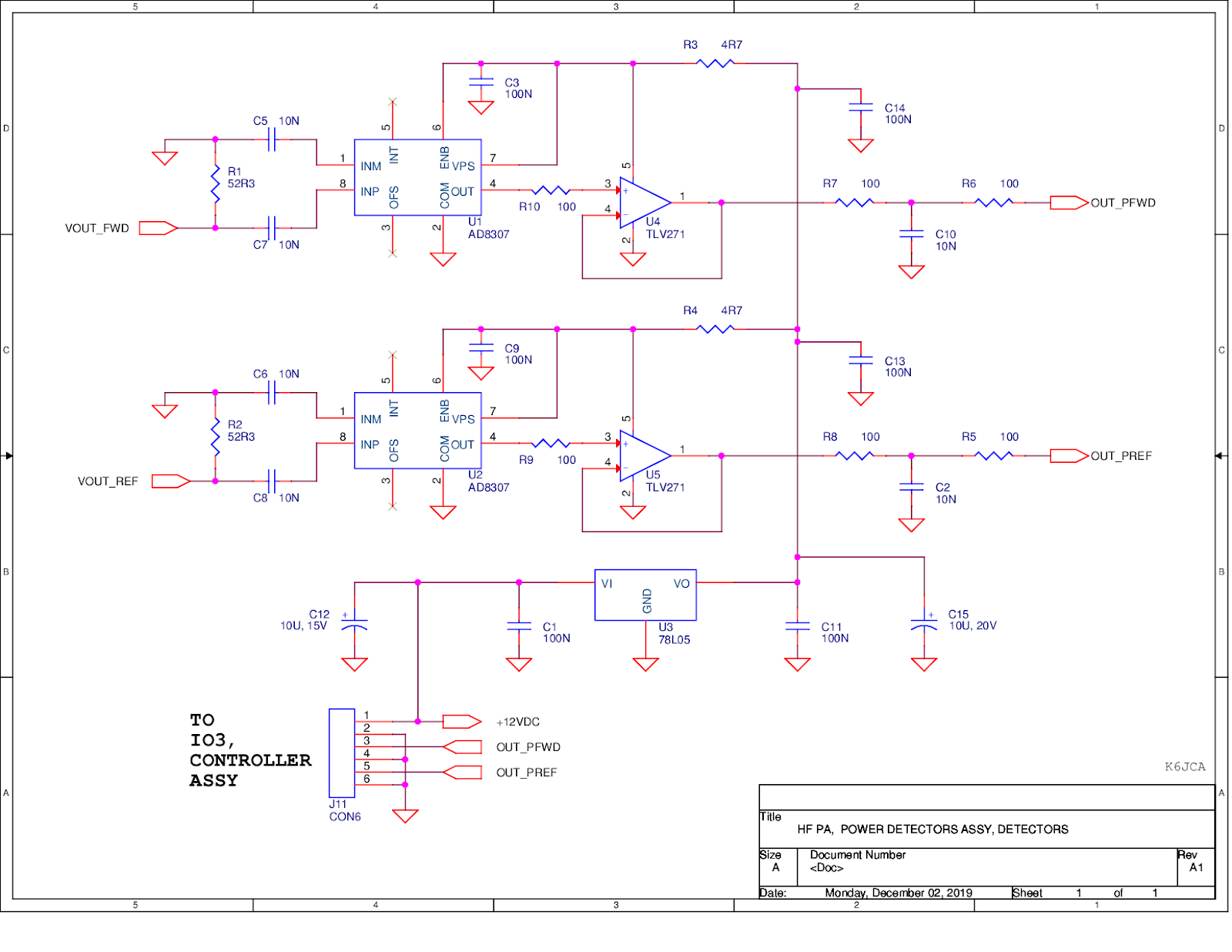
5. AD8307 Circuit:
The AD8307 circuitry is essentially the same circuit shown in the
datasheet. I have not incorporated the Intercept and Gain pots,
preferring to do these functions in the Return Loss Calculator circuitry
(described later in this post).
One AD8307 converts the Forward Power from the Directional Coupler to a
decibel-related voltage. The second AD8307 does the same for the
Reflected Power.
The two AD8307 ICs are in their own shielded compartment with 0.1uF caps (and
feed-thru caps) at the output and power pins of these two ICs to reduce the
chances of external RF fields affecting performance in unwanted ways.
Note that the second shunt resistor of each PI attenuator is also installed in
this compartment.
The AD8307 outputs have a transfer characteristic of about 25mV per dB of
applied power, with a DC offset (when no RF is applied) of (very) roughly 0.28
VDC.
Schematic, Return Loss Calculator:
(Click on image to enlarge)
Notes on the Return Loss Calculator Schematic:
(Important note: there was a design error in the original schematic that I
posted here (Rev. X). The schematic above is the
corrected schematic, and its revision-level is now
Rev. A1. Please see
Post 9
in this series for a description of the error and an explanation of the
fix).
1. Return Loss relation to SWR
The AD8307 output voltages represent, in dB form, the power applied to their
inputs. And thus Return Loss can be calculated via a simple subtraction,
implemented with a single op-amp:
where
Pi(dBm) is the output of the Forward path AD8307 and
Pr(dBm) is the output of the Reflected path AD8307 (equation copied
from
Wikipedia).
SWR is related to Return Loss by this equation:
Not a simple relationship, but knowing this equation, if I'm using an analog
panel meter to aid me in tuning, and if this meter's full-scale represents
30dB return loss (i.e. only 0.1% of the applied power is reflected back -- a
very good match!), then I can easily mark the meter's scale per the following
table:
(Click on image to enlarge)
A note on Return Loss meter orientation: when tuning an antenna
tuner using a Return Loss meter, the goal is to
peak the Return Loss
reading, which will then correspond to
minimum SWR. But I've been
adjusting tuners for decades by
dipping SWR meters for minimum SWR, so
the Return Loss adjustment method of peaking the reading seems awkward to
me.
A simple solution (it seems to me) is to install the Return Loss meter
upside-down. So, in my tuner, a Return Loss of 0 (infinite SWR)
corresponds to the meter's needle at the top of the meter (undeflected).
And when the tuner has been tuned for a 1:1 match, the needle will deflect to
its full-scale reading at the bottom of the meter's scale -- thus one dips the
meter for best SWR!
(Click on image to enlarge)
2. VF and VR circuits:
One of my goals is to incorporate a processor with A/D inputs (PIC or Arduino)
to perform the automatic tuning, and I thought it would be nice to use the
processor to calculate and display Forward Power using the AD8307 VF signal
(and perhaps calculate and display Reflected Power using VR).
Assuming the processor A/D is referenced to its VDD pin (+5VDC), I'd like to
have 4.5VDC represent the maximum applied power of +60 dBm (to give me a bit
of headroom).
Also, I would like the range of Forward Power represented by VF to be, at a
minimum, from 1 watt (30 dBm) to 1 KW (60 dBm). Plus, if I'm measuring a
30 dB Return Loss when Forward Power is 1 watt, then the Reflected Power will
be 1 milliwatt (0 dBm). And so VR must be just at least 0V when the Reflected
Power is 0 dBm.
So, VF and VR, in spanning the range from 0 to 4.5 volts, must represent, at a
minimum, a power range of 0 to 60 dBm.
If the AD8307's transfer function is 25 mV per dB, then multiplying this value
by 3 would result in a transfer function of 75 mV per dB, which would give us
a 60 dB span over the voltage range from 0 to 4.5 volts.
But why not have a bit more range? If I multiply the AD8307's transfer
function by 2 instead of 3, I will change the transfer function to 50 mV per
dB (500 mV per 10 dB). Assuming a 10-bit ADC referenced to 5 VDC,
measurement resolution would be about 0.1 dB, which would be perfectly fine in
this application.
And note that at 50 mV per dB, 0 to 4.5V will represent a 90 dB span, so I
could accurately measure power and Return Loss at powers well below 1
watt. (Theoretically, this would put the lower Forward Power limit for
accurate Return Loss measurements at 0 dBm (1 milliwatt), but as I'll discuss
below, the AD8307's specifications result, in this application, in a practical
lower limit of +10 dBm Forward Power for accurate measurements).
Op-amps U1A and U1B, configured as non-inverting amplifiers with gains of 2,
perform this amplification. And by connecting the AD8307 outputs
directly to their non-inverting inputs, I avoid any unnecessary loading of the
AD8307 outputs that might affect their gain.
Potentiometers R11 and R12 create a DC shift so that, when calibrated, +4.5V
represents +60dBm. U11B and U11C isolate these two pots from being
included in the gain-equations of the U1A and U1D feedback networks, so that
adjusting R11 and R12 won't also change the path gain.
The voltages at U1.7 and U1.8 should be about 0.75 VDC when R11 and R12 are
centered. I then adjust R11 and R12 so that, for a +10 dBm signal
applied to the Directional Coupler, VF (or VR) measures 2.00 VDC.
3. Return Loss Circuit:
U2 performs two functions. It subtracts VR from VF to create the Return
Loss measurement, and it also multiplies this result by 3.
The scaling factor of 3 was chosen so that a measurement of 30 dB of Return
Loss would be equal to 4.5V at VRL (VRL is the Return Loss signal that would
drive a processor A/D input). In other words, given the transfer
characteristic of VF and VR of 50 mV per dB, I'd like the Return Loss transfer
characteristic to be 150 mV per dB.
U2 also drives an analog panel meter so that I can use the tuner without
having a processor installed. The meter is 1 mA full-scale, and R19
adjusts the current through the meter so that 4.5V at VRL results in 1mA
through the meter. Thus, the meter would read 30 dB of Return Loss when
deflected to its full scale.
R24 compensates for differences in path-gain between the Forward and Reflected
paths. Because it is in the attenuator network attached to U2's
non-inverting input, it adjusts the gain of the Forward path (the gain
of the Reflected path being fixed).
But there's a potential problem -- changing the gain at this point also
changes, in effect, VF's DC offset as seen at U2's non-inverting input.
And because this change in DC offset at U2 is occurring simultaneously with a
change in the Forward path gain at U2, these two changes become inextricably
intertwined, and
I don't know by how much I should adjust R11 to compensate for this change
in offset.
The net effect is that VRL could be shifted slightly either higher or lower by
a constant amount. And thus Return Loss could be shifted, too, to be
either higher or lower than it should be.
If the shift is small, this shouldn't be a big deal. But it could become
a problem for larger shifts, depending upon how accurate one wants the Return
Loss measurement to be.
Fortunately, in my "one-off" build, the transfer characteristics of the two
AD8307 ICs are essentially identical at 25 mV per dB and so adjusting U2's
gain via R24 should be fine in this application -- I'm essentially just
setting the gains of each of U2's "legs" to be equal.
But in hindsight I would have approached path-gain compensation
differently.
For example, I probably would have made U2's gain fixed, without any pots (and
using 1% resistors) and instead had separate gain adjustments earlier in the
Forward path and the Reflected path. Pots could have been placed at the
outputs of the AD8307 ICs (per the datasheet), for example, or in the feedback
networks of U1A and U1D.
But that's hindsight.
4. Other notes:
0.1 uF caps are sprinkled liberally throughout the circuit and especially at
any connector to which a cable might attach, thus bypassing these connectors
to ground to (hopefully) prevent external RF fields that might couple into the
wiring from affecting circuit operation.
I've inserted 100 ohm resistors between op-amp outputs and 0.1uF bypass caps
(where these are used) to "isolate" the op-amp's output (and feedback network)
from the capacitive load and thus isolate this load's effect on the overall
amplifier phase-response and stability. (More info on this
here (Analog Devices),
here (TI), and
here (Microchip)). (Unfortunately, TI doesn't spec the output impedance of the LMC660 series,
so it's difficult to judge what the effect actually is. However, per my
bench measurements, stability seems fine).
I also roll-off the U2's response with C9 and C10, placing a pole at about 5
KHz -- there's no reason why this op amp needs a wide bandwidth.
OK, I believe I've covered the schematics. On to the build...
Build, Directional Coupler:
The Directional Coupler started out as a prototype on a piece of PCB stock
that would fit within the Tuner on the existing Capacitor-select board.
I tried some different orientations for the two transformers, such as
orthogonal to each-other, but Directivity was only about 20 dB, so I went back
to the implementation I'd used in this post:
http://k6jca.blogspot.com/2015/01/building-hf-directional-coupler.html, which was:
I changed the current-sense transformer's core size (see discussion above) and
bread-boarded the circuit:
Measuring Directivity:
With the implementation shown above Directivity measure 45 dB or better from 1
to 30 MHz. But when I added additional compartment shielding and the 22
dB PI attenuators, worst-case Directivity dropped from 45 dB to 35 dB:
Note that the 30 MHz marker in the image above shows 85 dB of
attenuation. But we need to factor out 50 dB of attenuation (27.6 dB
coupling factor plus the PI Attenuator's 22.2 dB of attenuation). The
result is 35 dB of attenuation, which represents the Directional Coupler's
Directivity.
Here's that implementation:
(Note that you can just see the AD8307 circuitry at the far-left of the image
above. Although present in the photo above, this circuitry had not yet
been installed when I made my Directivity measurements.)
Also, if you look closely, you can see some yellow Teflon insulation on the
end of one of the voltage-sense transformer's secondary winding. There
is actually Teflon insulation on both ends of this winding. Both ends
are side-by side on the transformer and there is a high voltage potential
between them (one end being grounded and the other end connected to the
transmission line).
There is also a little rectangle of Kapton tape mounted under voltage-sense
transformer on the bottom of the compartment. It provides a bit more
voltage isolation between the transformer windings and chassis ground.
(I also tested an implementation using a 2643625002 core for the current-sense
transformer. I saw no difference in performance between it and the
FT50-43 I am currently using.)
Return-Loss Uncertainty due to Directivity:
Now that I knew the Directional Coupler's Directivity, I could determine
Return-Loss Uncertainty.
Note that with a worst-case Directivity of 35 dB, there will be an increasing
uncertainty in Return Loss readings as the Return Loss approaches its
theoretical maximum of 35 dB (Return Loss cannot be larger than the
Directivity). This uncertainty is shown in the table below, per the
calculator found here
bytecollector.com/library/DirectivityErrorCalc-w-SWR.xls:
(Click on image to enlarge)
So, given my planned-for maximum Return Loss reading of 30 dB and a worst-case
Directivity of 35 dB, the
actual Return Loss for this reading (and
excluding path errors such as AD8307 accuracy) would lie somewhere in the
range between 26 and 37 dB, which represents an actual SWR that would be
between 1.03 and 1.1 -- still quite acceptable.
AD8307 circuit implementation:
The AD8307 ICs are SOIC-8 packages. I find that such a small size can be
a headache to prototype with (unless, of course, one has a PCB with
appropriate component footprints), so I purchased some small SOIC prototyping
boards from eBay. These greatly facilitate wiring to the IC pins.
(Alternatively, I could have purchased these ICs in DIP packages).
(I later added copper tape to shield the sides of the AD8307 chamber, and a
copper top will be added over the entire assembly after I finished mounting it
in the tuner chassis).
Build, Return Loss Calculator:
When I finished my Directional Coupler build I discovered, if I placed it in
the Tuner chassis, there wasn't much additional room available on the
Capacitor-selection board for me to add the Return Loss Calculator
Circuitry.
And given the fact that my junk-box potentiometers were all designed to mount
end-on, I decided instead to build the circuit on a small piece of
plated-through perf board that I would mount
vertically on the bulkhead
shield that separates the Tuner's RF compartment from the Control
compartment.
Although the two ICs are DIP ICs, the passive resistors and capacitors are all
surface mount (0805 packages).
Here's the build, shown un-annotated and also annotated with I/O names and
potentiometer reference designators added:
The board was notched in two places due to mechanical interference issues with
two pre-existing mounting screws, given the tight space that I was trying to
mount it into.
Incorporating the Directional Coupler and the Return Loss Assemblies into
the Tuner Chassis:
Here's a picture showing the installed Directional Coupler Assembly and Return
Loss Calculator Assembly. (You can see the latter's pots next to the
bulkhead divider).
(Note that I did not remove the SMA connectors on the Directional Coupler
assembly. They are left there in case I need them for future
testing.)
Below I've installed a copper plate (cut from a sheet of 26 gauge copper) over
the top of the RF compartments, with bent-down tabs tacked to the side walls
in 5 places.
Calibration Procedure:
1. With the Directional Coupler's output unloaded (
open load) and
disconnected from the Tuner's L-Network circuitry, and with a +10 dBm 3.5 MHz
signal applied to the Directional Coupler's input, make the following
adjustments:
- Adjust R11 so that VF is 2.00 VDC
- Adjust R12 so that VR is 2.00 VDC
2. With the input to the Directional Coupler still +10 dBm at 3.5 MHz,
connect a
calibrated 75 ohm load to the Directional Coupler's output
and make the following adjustments
-
Adjust R24 so that VRL measures 2.10 VDC (equals 14 dB Return Loss times
0.15V/dB)
- Adjust R23 so that the Panel Meter deflects to 47% of Full Scale.
Design Verification Measurements:
1. VF and VR versus Input Power.
This test is performed with the Directional Coupler's output unloaded (i.e.
open, so that Forward and Reflected powers are identical) and after R11 and
R12 have been calibrated to give equal readings of 2.00 volts at VF and VR for
a +10 dBm input signal. It measures the response, versus signal level,
of VF and VR.
(Click on image to enlarge)
Note that the gain of VF and and the gain of VR
are essentially identical. (There's no guarantee that this will
be true for all AD8307's, though).
2. VRL versus Zload:
This test measures the Return Loss voltage versus different loads connected to
the Directional Coupler's output. Note that the Zload is resistive
rather than a complex impedance.
(Click on image to enlarge)
For the three loads I used, the measured Return Loss is close (error under a
dB) to the loads' actual Return Loss (per my HP 8753A). This error is
quite adequate for my tuner application, which is not meant to be a lab-grade
measurement device.
3. Step Response, VRL
This test checks VRL's step-response to a change in Return Loss, measuring the
amount of time it would take the VRL reading to settle down after, for
example, a change to the tuner's L-Network settings.
But rather than performing the test by changing the Directional Coupler's load
in a "step" fashion (for which I'd have to design some sort of fast-switching
circuit), I instead "mimic" a change in load impedance by taking advantage of
the VF and VR circuits' characteristics at low signal levels.
This is an important point:
specifically, if the drive to the Directional Coupler is less than +10 dBm,
and if the load itself is an accurate 50 ohm load (Return Loss > 30 dB),
the measured Return Loss
will be a function of the input power level, rather than a function of
the load attached.
This effect is mainly due to the fact that, at low power levels, the VF and VR
op-amp outputs will clamp to their negative rail -- they cannot go below 0
volts.
Thus, even with a 50 ohms load is connected to the Directional Coupler's
output, Return Loss will appear to be very poor if the applied power level is
very low, as I demonstrate in this table:
As one can see, because VR cannot go below U1's lower power rail of 0V, the
delta between VF and VR is artificially reduced at low power levels. And
so Return Loss erroneously appears to worsen.
One important conclusion from this data: If the input power
applied to the Directional Coupler is less than +10 dBm, the Return
Loss measurement could be wrong. So tuning should only be done
when VF measures at least 2.0 VDC (i.e. input power at least +10
dBm).
(But keeping the input power above +10 dBm shouldn't be an issue. After
all, +10 dBm represents 10 milliwatts.)
(Note, as power decreases, even if VR weren't clamped to 0V by U1, the same
effect would occur at some lower power level because the Reflected path's
AD8307 transfer-characteristic limits-out at at the lower limit of its
input-power specification.)
We can use this behavior to mimic a step-change in the impedance seen by the
Directional Coupler's output.
Here's an oscilloscope capture of VRL step-response to a step-change in the
signal level applied to it (via my Fluke 6060B). Although I'm stepping
the level from -20 to -10 dBm, which, per the previous table, should give a
VRL transient from 1.5 to 3 volts (a Return Loss step from 10 dB to 20 dB),
the Fluke's attenuator relays, as they change, briefly create an attenuation
larger than -20 dBm before they step to +10 dBm. The result is that VF
goes to 0 volts (rather than starting at 0.5V) before stepping to 1.0
volt. VR is 0 volts in both cases, and thus VRL (being equal to VF-VR)
steps from 0V to 3V.
In other words, this test mimics a step-change in Return Loss from 0 dB to 20
dB.
(Click on image to enlarge)
VRL settles down within about 7-8 msec of the initiation of the step
transient.
4. Impact of Directional Coupler circuitry and the Additional
Grounded Shields on Tuner Match Performance:
This test checks if the addition of the Directional Coupler assembly (and its
shields) has any effect on the Tuner's "match-space." This test is
performed at 30 MHz (the highest frequency I'm specifying for this tuner) to
accentuate the negative effects of any stray parasitic components.
The test is identical to the one described in this post:
http://k6jca.blogspot.com/2015/09/antenna-auto-tuner-design-part-7-build.html
And here are the results:
(Click on image to enlarge)
Below are the results from my prior testing (from Part 7 of this series of
posts):
(Click on image to enlarge)
These two plots appear identical to my eyes. Therefore, the incorporation of
the Directional Coupler assembly into the tuner has little, if any, effect on
the tuner's match-space.
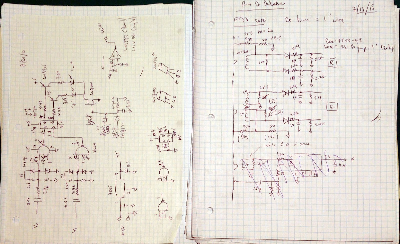
Other Notes:
I actually breadboarded the R, G, and Phase Detectors just to make sure that,
conceptually, they worked. And they did, but I only did a minimal amount
of testing.
Here is an image of the schematics:
(Click on image to enlarge)
Note that the schematics are not entirely representative of the final
breadboard circuit (they are included here only for sake of completeness).
For example, after I smoked one of the resistors in my first voltage sampler,
I changed the two resistive transmission-line voltage samplers to instead be
capacitive voltage dividers (each divider became a 1.7-11 pF variable cap (to
the transmission line) in series with 120 pF fixed cap (to ground)).
I also needed to add a DC path to ground (yet high impedance at RF) at each
capacitive dividers' voltage-divider node. I did this with a 2.5 mH
inductor connected in parallel across each 120 pF cap.
Also, I deleted the 2N7000 in the phase detector -- the goal was to have the
LEDs turn ON only when RF was present. But, given the 2N7000 turn-on
voltage, this wasn't working as planned for the RF power levels I was testing
at. No problem, as I didn't really need to do this to verify detector
functionality, so I simply grounded the 2N7000's Drain to ground.
And the Vv and Vi signals are defined per the definitions shown in my post
(post 6 in this series) on Match Detection.
OK, that ends this post!
Part Nine of this blog series is posted here:
http://k6jca.blogspot.com/2016/01/antenna-auto-tuner-design-part-9-build.html
And please note: The "final" schematics could have changed from the
versions included above, in this post. The
final "release" schematics can be found in Part 10 of this
series:
http://k6jca.blogspot.com/2016/01/antenna-auto-tuner-design-part-10-final.html
Links to my blog posts in this Auto-tuner series:
Part 1: Preliminary Specification
Part 2: Network Capacitor Selection
Part 3: Network Inductor Selection
Part 4: Relays and L-Network Schematic (Preliminary)
Part 5: Directional Coupler Design
Part 6: Notes on Match Detection
Part 7: The Build, Phase 1
Part 8: The Build, Phase 2 (Integration of Match Detection)
Part 9: The Build, Phase 3 (Incorporating a Microcontroller)
Part 10: The Final Schematics
Links to my Directional Coupler blog posts:
Notes on the Bruene Coupler, Part 2
Notes on the Bruene Coupler, Part 1
Notes on HF Directional Couplers (Tandem Match)