
The venerable HP 8640B Signal Generator has long had a place of honor on many an engineer's workbench. But these generators are becoming long in tooth and some common modes of failure have appeared.
Two failures that one often sees in these generators are broken gears in the "Peak Deviation and Range Switch" Assembly, and missing rotary-switch wipers on HP's custom rotary switch assemblies -- these rotary switches are used in the "Peak Deviation and Range Switch" Assembly and in the "Output Level" Assembly.
Repairing Gears and Switch Contacts in the "Peak Deviation and Range Switch" Assembly:
As I've noted, above, the plastic gears in the Peak Deviation and Range Switch assembly are prone to cracking and, in the worst case, falling apart. Here are some examples from several different 8640B generators:

Several web sites discuss gluing cracked gears back together (see links at end of this post), but a better solution (in my opinion) is to replace the flawed plastic gears with brass gears.
At this time (September, 2018), there is at least one manufacturer selling brass replicas of the three 8640B gears most likely to fracture (the gears are sold either as a set of three or individually):
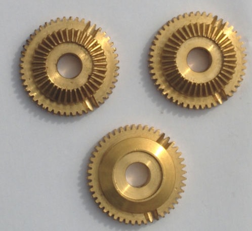
I purchased my set on eBay. You can search eBay for "HP 8640B gears" and check if they are still available. These gears do not replace every plastic gear in the assembly, just the three large ones, as these are the three most likely to crack.
Another common problem is that the "wiper" contacts on the rotary switches in this assembly (or in the Output Level Assembly) can sometimes fall off.

These wipers are each normally held onto its round clear plastic switch "rotor" with two small plastic nipples extruding from the round rotor's clear plastic surface. With age, however, these nipples can weaken and, if a generator experiences mechanical shock or vibration, the nipples can break loose and wiper contacts will no longer press down against the PCB traces below them or, in the worst case, they can completely fall off the switch assembly and into the instrument.
Peak Deviation and Range Switch Assembly Removal:
The 8640B's Operating and Service Manual has detailed instructions for removal and disassembly of this module. In my manual (printed April, 1978), this assembly's removal and disassembly is discussed in Service Sheet D, "A9 Assembly Removal and Disassembly", on page 8-88.
The instructions on the Service Sheet are self-explanatory when combined with the companion "Illustrated Parts Breakdown" illustration. But there are a few instructions that, I believe, need better explaining (or a slight change in procedure). I'll explain these, below:
Original Instruction 1: Set PEAK DEVIATION and RANGE switches to fully ccw.
My modification to Instruction 1: Set PEAK DEVIATION switch to fully ccw, but set RANGE switch to the 2-4 MHz range (two clicks clockwise from fully ccw).
This will place one of the grooves in the plastic portion of the switch coupler in a vertical position, which I find makes it a bit easier to withdraw the assembly. See picture, below:

(NOTE: After the assembly has been removed from the chassis, I put the RANGE knob back onto the assembly's RANGE switch shaft and turn it fully ccw, as was the intention of the original instruction.)
Instruction 5 (Removal of the assembly), note that there are lock washers on the threaded shaft assemblies (these normally protrude through the front panel). Be aware that they might fall off while you are pulling the assembly out of the chassis.

After removing the assembly from the chassis, disassembly can begin. Below is the Peak Deviation and Range Assembly that I will be working on. You can see that a large chunk of one of the gears is missing. (It is also missing three switch wiper contacts, which I will repair below, too).

Before continuing with disassembly, if you intend to repair any of the wipers on the switch rotors, I recommend noting where the contacts are for the three round clear plastic switch rotors when the two rotary switches are in their fully ccw position (the two pictures, below, are taken with the Peak Deviation and Range switches both in their fully ccw positions, per the manual's instructions).


Instruction 6 instructs us to desolder the three wires attached to the potentiometer terminals. I prefer to desolder these wires at the PCB. Be sure to note which wires go where (I took a photo rather than trust my memory).

Perform Instruction 7 (removing the retainer ring at the front of the potentiometer shaft), but before proceeding with the next instruction (Instruction 8), you first need to remove the coupler at the back end of the Range Switch shaft, as shown below (this step is not mentioned in the instructions):

(Note: the Range Switch in the photo, above, is in its fully ccw position).
Instruction 8 calls for the removal of a retainer ring. I've done this several times without "Retainer Ring Pliers", but I finally purchased a pair. Having now used them, I strongly recommend them -- they make the task of removing and installing this type of retainer ring so much easier.
(Note that the Retainer Ring Pliers tip diameters needs to be 1 mm (0.039") to fit into the holes at the end of the retainer ring.)


(Channel Lock makes a similar "Retaining Ring" pair of pliers. They are available through Amazon).
Continue with the manual's disassembly instructions.
(Note: if you are only replacing the gears and not also repairing the wipers on either of the two side-by-side rotors at the front of the assembly, you can stop disassembly after completing instruction 14 and jump to my "Installing the Brass Gears" section, further below.)
At the end of Instruction 16, the final two switch rotors can be removed from the switch shafts. Mine are shown below.

One of the switch rotors should have two wipers, but both of these broke off along with their mounting nipples. Fortunately, there is a spare set of nipples 180 degrees away from the original set, and I can mount the wipers onto these nipples, instead.
(Note: rotors in later versions of the 8640B might also have two white plastic "bumpers" (load levelers) installed on them. If you move the wipers to the spare set of nipples, you will need to move these bumpers 180 degrees around the rotor, too. I discuss this further, below, in the "Output Level" Assembly's repair instructions.)
The other switch rotor has three wipers, of which one broke off. The other two seem to still be solidly attached, so I've decided to glue the wiper back onto its original location, even though there are no nipples, rather than move all three wipers 180 degrees to the untouched nipples.
I use a drop of Super Glue (cyanoacrylate) to glue each metal wiper to its plastic rotor.

For wipers that have fallen off, I'll put the drop onto the rotor first and then press the wiper into it and hold it down (using a pair of tweezers). For wipers that are still on the rotor, I'll put a drop on the top surface of the wiper, and this drop spreads across its surface to the plastic on all sides of the wiper.
I will then let the super glue "cure" for the better part of a day (just to be sure). (Note that others have used 2-part epoxy successfully -- refer to the links at the end of this post).
Here are the three switch rotors from the assembly. I have applied drops of super-glue to all wipers, even those that have not yet fallen off.

A quick test of the bond of the "nipple-less" wiper to its plastic rotor.

Also, while the assembly is apart, I recommend cleaning the switch contact traces on the printed-circuit boards by wiping them with a clean cloth.
Now reassembly of the module can commence. This is simply the reversal of the manual's disassembly instructions. But instead of mounting the original three large plastic gears that are prone to cracking, I will replace them with the new brass gears, as follows:
First, follow Instruction 17.b and ensure that both switches are in their fully ccw position (which they should already be).
Then install the 3-wiper and 2-wiper rotors per Instruction 17.c. Note the wiper positioning of the two rotors in the photo, below. (By the way, my "TOP" notation specifies that this side of the assembly is UP when the module is installed in the chassis and the chassis placed in its normal operating position, not upside-down):
Now start working backwards from instruction 16.

Installing the Brass Gears:
After instruction 15, you will begin installing the three brass gears. Two of these are "combination gears" and one is a "spur gear":

Note that one of the combination gears does not need set screws.
The diagram below shows the location of these gears:

In Instruction 14, mount the brass "spur gear" (this is the gear with only one set of teeth, not two), identified as item 40 in figure 8-97 of the manual. Note that one of its two set screws should be positioned on the "flat" surface of the shaft, but do not tighten them yet.
In Instruction 13, mount a brass "combination gear" (item 14 in figure 8-97) in lieu of the original plastic gear. Note that a "combination gear" has two sets of teeth, not one. And note that one of the gear's set screws should also be positioned towards the flat side of the shaft, but don't tighten the set screws yet! (keep the screws loose so that you can adjust this gear's position after you complete Instruction 8, per the procedure in Instruction 17.d, as I will discuss, below).
In Instruction 12, replace the plastic "combination gear" (item 19 in figure 8-97) on the T-shaft with its brass equivalent. Note that this gear should have no set screws (although the brass gear has holes for set screws).
Try to align the planetary gears close to vertical when you slide it onto the solid Range Switch shaft.

When you've completed Instruction 8, you will need to rotate the four-wiper rotor at the back of the assembly to its proper position before tightening the set screws of the combination gear (item 14 in figure 8-97). This is best done by unmeshing the combination gear (with the set-screws in it) from the smaller planetary gears so that the T-shaft can rotate freely.

You will have successfully aligned the rear rotor when the wipers on the rotor and the two small planetary gears that contact the brass combination gears are all vertically aligned.
You can now remesh the gears and tighten the set screws on both of the brass gears that have set screws, per the pictures, below. (Note, again, that one set screw of each gear should align with the flat surface of the appropriate shaft).


Verify that all gears are positioned properly (for example, none of the three brass gears should be touching any PCB (their brass could short out traces!). And all set screws should be tight (four screws, total). Then temporarily install the two large knobs and rotate each, testing that the switches turn without significant resistance or binding. (Loosen the gears' set screws and reposition them slightly if there seems to be an issue).
After completing this alignment, reinstall the Shaft Coupler (that was just after instruction 8, above) onto the rear of the Range switch shaft and continue with the reassembly, following the manual's instructions in reverse order.
When you reach instruction 5, before you remove the Range switch's knob (so that you can install the assembly into the chassis), rotate it two clicks clockwise from its fully counter-clockwise position. The rear groove in the plastic coupler should now be vertical (if you've correctly installed the shaft coupler):

Now remove any knobs that you've temporarily installed and put the lockwashers back onto the switch threads:


Screw on the two nuts onto the switch threads, attach the knobs, and you are done!
Here is my reworked module with its three new brass gears, installed back in my generator:

That's it for my Peak Deviation and Range Switch Assembly repairs!
Repairing Switch Contacts in the "Output Level" Assembly:
There is also a plastic switcher rotor at the rear of the "Output Level" assembly. It, too, can lose its wiper contacts, as I discovered while tracing down a problem in a different 8640B...
This 8640B had very low output, and I traced this problem back to a missing wiper on this rotor (which caused the MOD signal to the modulator assembly to be "open").
Here's the assembly. You can see the switch rotor mounted on the back of the assembly.

Again, the manual gives comprehensive instructions for removal of this assembly (refer to Service Sheet A, "A1 Assembly Removal Procedure", on page 8-82, and its companion drawing on page 8-83).
Before removing the Output Level assembly, I recommend rotating the Output Level switch to its "-130 dBm" position. Its wiper contacts will then be in the position shown, below:

Below is this assembly, removed from the chassis. If you look closely you will notice that the third wiper (of three) furthest from the outer edge of the rotor is missing.

(And if you look closely you will also see two white "bumpers" also mounted on the rotor. These are on the opposite side of the "circle" from the wipers and act to provide a counter-force to help keep the wipers in contact with the gold-plated traces below them.)
I haven't seen these bumpers on early models of the 8640B, so I suspect they were added in a later revision -- this 8640B has a serial number prefix of 2153A (i.e. built (or revised) in 1981), whereas the unit whose Output Deviation and Range Switch assembly that I repaired, above, has no bumpers on its rotors and its serial number prefix is 1745A (1977 build (or revision)).
Service Sheet A does not discuss the disassembly of the Output Level Assembly, but it should be obvious from inspection after you've removed the assembly from the chassis. I used the following procedure:
1. Check that the Output Level switch has been rotated to its -130 dBm position (i.e. fully ccw). Note where the wiper contacts are in relation to their PCB traces.
2. Note the colors of the wires going to the potentiometer from the PCB. Then unsolder them either at the PCB or at the pot.
3. Remove the two long screws holding the potentiometer bracket to the rear of the step-attenuator and remove the potentiometer and bracket.
4. Pull out the potentiometer shaft extension that passes through the center of the step-attenuator's shaft.
5. Now remove the Retainer Ring. (Use a pair of Retaining Ring Pliers!):

6. You can now remove the washer, spring, and the switch rotor.
With the rotor removed, you can replace any missing wipers and glue all of them to the rotor (I use drops of super glue). (And now would be a good time to wipe the switch PCB contact-traces with a clean cloth).
IMPORTANT NOTE:
Because the two nipples for the missing rotor were also missing, I mounted the three rotors on the spare set of nipples 180 degrees from the original set (using a drop of super glue for each wiper, as I did for the other assembly). And I moved the two white bumpers 180 degrees, too, per the picture, below:

Reassembly is just the reverse of disassembly. Note that having a pair of "Retaining Ring Pliers" makes the reinstallation of the retainer ring a snap, rather than a chore replete with much swearing.
Sources of Wiper Contacts:
If a wiper contact falls off of a rotor, it might be lost forever. To check, though, I would recommend removing all covers (top, bottom, and sides) and vigorously shaking the unit over a terry-cloth towel (the latter to prevent a wiper from bouncing away). Turn the 8640B upside down, sideways, etc., and shake! If you are lucky you will find the missing wiper on the towel.
But if the wiper is gone forever, there is still hope.
A number of people have fashioned their own wiper from other materials, for example, from a relay contact. (See the links below, at the end of this post.)
But the ideal solution is to find a junker piece of HP test gear that uses HP's custom slide switches -- there's a good chance that the slide switches have the same contact wipers, and you can use these wipers in the 8640B.
For example, I found an HP 8013B Pulse Generator at the De Anza fleamarket. Per the seller it was non-functional (which I later verified at home), and the price was right: $10.00.
Its custom slide switches (circled below) all use the same wiper contacts as are used in the 8640B.

Here is 8013B's front panel PCB:

And below is the back side of one of the slide switches, after it has been removed (they slide right out). Note that this particular switch has two wipers. Just remove the tops of the nipples and you have two spare wipers!

8640B Hints and Kinks:
Additional notes on the 8640B:
1. If the display shows all zeroes rather than the frequency, and it remains all zeroes as you turn the frequency knob, before you abandon hope first check the position of the Time Base toggle switch on the unit's back panel. It should be down, in the INT position, not up in the EXT position.
2. HP seems to always use screws with "Pozi-drive" heads. I recommend using matching "pozi-drive" screwdrivers -- they are less likely to bung up the slots in a screw's head.
Useful 8640B Links:
Manual PDFs:
Several versions of the HP 8640B Operating and Service Manual can be found at the BAMA website:
http://bama.edebris.com/manuals/hp/8640b/
Other links:
http://antiqueradios.com/forums/viewtopic.php?p=1055125 (Bulb Replacement, Gluing switch wipers, and don't store an 8640B on its end)
https://www.eevblog.com/forum/repair/hp-8640b-signal-generator-switch-disk-plastic-gear-repairs/ (Making contact wipers and using epoxy to hold them)
http://jvgavila.com/hp8640b.htm (Using relay contact as wiper replacement)
http://jvgavila.com/wb1.htm (Using two-part epoxy to hold wipers).
https://www.ve7ca.net/TstH86.htm (Many useful repair notes!)
http://www.wb0smx.net/?p=2023 (Detailed gear replacement (but with gears from a different manufacturer). Many pictures!)
(And googling "HP 8640B repair" will return many other links).
Standard Caveat:
As always, I might have made a mistake in my equations, assumptions, drawings, or interpretations. If you see anything you believe to be in error or if anything is confusing, please feel free to contact me or comment below.
And so I should add -- this information is distributed in the hope that it will be useful, but WITHOUT ANY WARRANTY; without even the implied warranty of MERCHANTABILITY or FITNESS FOR A PARTICULAR PURPOSE.


10 comments:
Thank you for the guide on 8640B repair! Using it, I was able to successfully repair one of my 8640B that had stopped working.
Regards,
Darryl
K0GV
Thank you so much - your info is a massive help
73 Symon G4DND
If one of the wipers is missing on the range switch rotor (the one that contacts the inside of the circular PCB track) will that prevent the range from changing and hence everything else stops working?
Possibly, but unfortunately I do not have the time to dig through the schematics.
Regarding "everything else stops working"...
If the Frequency readout is '0' but you have RF output, check that the Ext/Int Reference toggle switch on the back panel is set to Internal.
If the Frequency readout is '0' and there's also no RF, then possibly the oscillator module is not oscillating.
A great resource is the "HP-Agilent-Keysight-equipment" group on groups.io. Many knowledgeable members, and I would recommend posting your questions there.
- Jeff, k6jca
All fixed now, thank you Jeff. See also my blog post on the repair at http://blog.depannone.com/?p=577
Thanks. I've bought several really cheap lately-they all have this exact problem (a couple have the gear AND the finger contact issue) and are otherwise in great shape. Such a shame. Don't need them. They just make me remember a time that I felt useful as an electronic technician. This might be the end of an era with this problem though.
Excellent writeup. Do you have this writeup in a PDF document?
Thanks
Denis
Thanks, Denis. No, the write-up is only on this blog.
- Jeff
Hi Jeff super good blog. I am dealing with replacing the fingers which was going well and suddenly there is no rf the attenuator switch seems to do nothing. I noticed 1 of 3 wipers missing on the attenuator switch could that stop the rf output? I measured the Oscillator A3 output at -30db feeding the divider but the signal just disappears coming out of the divider into the agc/amp. Not sure if I put the the 3rd wafer (band switch) with the 4 wipers in the right position if that is incorrect will that cause no rf but the counter works fine thru out.
Thanks Roy
Hi Roy,
It might be possible that a missing wiper is causing your problem. Try putting the attenuator on the +20dB output range and see if there is any signal in that position. If there is signal in that position, then perhaps the problem is due to the missing wiper?
Other than that, there are many possible causes for no RF output -- maybe it's the missing wiper (try replacing that first), but it also might have been caused by something getting screwed up or not connected or connected incorrectly if you disassembled part of the equipment and then reassembled it.
Troubleshooting equipment can be quite time-consuming, which becomes much more of a problem if trying to troubleshoot equipment remotely. And unfortunately, I don't have the time.
I would like to suggest that you pose your questions to the HP-Agilent-Keysight-equipment list at groups.io. You can find it here:
https://groups.io/g/HP-Agilent-Keysight-equipment
It's a very knowledgeable group of people with much experience fixing HP gear. After you join the group, you can create a new topic with your questions regarding the 8640B.
My apologies that I cannot be of more help.
Best regards,
Jeff, k6jca
Post a Comment