Tuesday, January 5, 2021

Designing a Multiband Doublet Antenna

An Introduction to Doublet Design Validation

This post will not tell you what length of wire or feedline to use for your doublet.  

Instead, I will describe a procedure by which you can model an antenna and feedline (that either you or someone else might have specified) so that you can determine its performance with respect to SWR and Power Loss, and adjust lengths and type of ladder-line quickly, "in the computer," to (hopefully) minimize any "in the field" trimming you might need to do.

Much has been written about doublet antennas (just Google "Doublet Antenna"!).  Often the advice to a ham is simply to "get a wire as high in the air as you can and feed it with ladder-line."

Such advice leaves much to be desired.  How long should the antenna be?  And how long (and of what impedance) should the ladder-line be?  A poor choice can result in much frustration when you discover that your antenna tuner cannot tune your antenna to a reasonable SWR on your favorite ham band.

Fortunately, using a couple of free software packages, this post will show you how to model the effect of:

  • Antenna radiator length
  • Ladder-line impedance and its length
  • Balun impedance transformation (should you want to try, for example, a 1:4 balun impedance-transforming balun)
  • Coax loss (if there is coax attached between the ladder-line and your system's antenna tuner).

But first, a quick introduction to the "Doublet" antenna...

What is a Doublet Antenna?

A Doublet antenna is simply a wire antenna consisting of two antenna arms of equal length and fed with ladder-line.  The Antenna portion of the doublet could be resonant or non-resonant on the ham-bands.

Typically, the ladder-line feed line is terminated at an antenna tuner, which is used to tune the impedance presented at that end of the feedline to something acceptable by the transceiver (e.g. 50 ohms).

And sometimes a run of coax connects the end of the ladder-line to the antenna tuner (or even directly to the transmitter).  This usually occurs when the ladder-line length is short and not close enough to the antenna tuner for direct connection (e.g. the ladder-line for a G5RV doublet), or if you want to run the transmission line through the wall of a house to your operating position.

Often the impedance seen at the "transmitter" end of the ladder-line will not be 50 ohms (that's the reason for the antenna tuner, after all).  Remember that coax can have significant loss (especially on the higher bands) as the SWR of the load it sees worsens.  For this reason, keep the coax run as short as possible.

If coax is used for part of the feedline, a current-balun (for example, a 1:1 common-mode choke) should be connected between the coax and the ladder-line to ensure that the antenna system remains "balanced" (and that the coax-shield does not radiate).  (But you will sometimes see coax connected directly to ladder-line without a common-mode choke). 

Sometimes you'll see a 1:4 balun used in lieu of 1:1 Common-mode Choke.  Do not add a 1:4 balun unless you know its effect (and have designed for it) on the impedances presented by the ladder-line at at its "transmitter" end.  (Fortunately, this effect can be modeled, and I will explain how to add an impedance transformation for modeling purposes later in this post).

Also -- be aware that some baluns are "voltage" baluns and some baluns are "current" baluns.  Current baluns, being common-mode chokes, are preferred because they will help keep you system balanced and minimize coax radiation.

If, through simulations, you discover you need a 1:4 impedance transformation and you only have a voltage balun, add a 1:1 current balun in series with it (place the 1:1 balun on the 50-ohm port side of the 1:4 balun) to get both common-mode choking and the 1:4 impedance transformation.


Modeling a Doublet Antenna System:

I use two steps to model a doublet antenna system.

The first step is to create a .S1P file (i.e. "Touchstone" Format File) containing the Antenna's Reflection Coefficient values, expressed as one-port S-parameters, calculated at its feedpoint over a specified range of frequencies.

To create this file, I will use the free Antenna Modeling software package, 4nec2.  You could also use EZNEC+, Version 6 (or later) to create S1P files.

This antenna S1P file, after it has been created, is then imported into another free software package, SimSmith. Given the antenna's impedance characteristics over frequency (contained in the S1P file), Simsmith will allow us to add a feedline (or combination of feedlines) and analyze the effect of feedline characteristics (e.g. length, impedance, and loss) on SWR and overall feedline power-loss when connected to the doublet antenna represented by the S1P file. 

Using SimSmith, you can vary the length of the ladder-line in real-time, while watching SWR nulls (and power-loss) change with frequency, to find a length that best matches your goals.  

Let's start with an example and go through the steps...

Step 1:  Model the Antenna and Create an .S1P file:

 I'll model a G5RV doublet at 30 feet using 4nec2.  Note that this model is of the antenna radiators only.  It does not include the feedline.

First, I need to create the antenna.  To do this, I go to the "Edit" tabe and select "Input (.nec) file", as shown, below.


Another window will pop up.  Select the "Geometry" tab, then enter in the coordinates of you wire endpoints.  I like to use 3 wires -- two long wires connected together with a very short wire.

This very short "middle" wire is where I will place the voltage driving source (for the calculations), and having two long lets allows me to position each radiator differently in space, for example, if I had one leg running horizontally and one leg running towards ground, or if I had both legs running towards ground in an inverted-Vee configuration.

In this example, though, both of the "radiator" legs run horizontally. (By the way -- all three wires radiate, but the two long wires are the main radiating wires, and I will refer to them as the "radiators").  Refer to the image, below:

As a check, make sure your dimensions are using the correct units!  I prefer to use feet, but others will prefer meters.  You can check (and change) the units under  the "Settings" tab in the "Main" window.

Next, I define the driving source.  I use a voltage source, and I place it in the middle wire of my model's three wires (wire "tag" = 3).

Note that this wire consists of only 1 segment.  And it is into this segment that the source is inserted.  

Under the "Freq./Ground" tab, enter the frequency for which you'd like the antenna's radiation pattern to be plotted:

Next, if you'd like to add some notes, add them under the "Comment" tab.


After you have created the antenna model, added the source and radiation-plot frequency, and added comments (if any), you will need to save the file as a .nec file.  To do this, go to "File" and select "Save As":


This will open a new window pointing into the folder into which the .nec file will be written.  Type in the name you'd like the file to have and click "Save":


After you've created the antenna a window should pop up showing a visualization of it.  (If you don't see this window, press "F3" on your keyboard).  Make sure the antenna looks the way you've planned it to look, and that the source is placed where you planned it to be.


Next, we need to generate a file with the antenna's S11 S-parameters.  To do this, we first need to generate a frequency sweep.  To set this up, go to "Calculate" on 4nec2's main window and select "NEC output-data", as shown below.

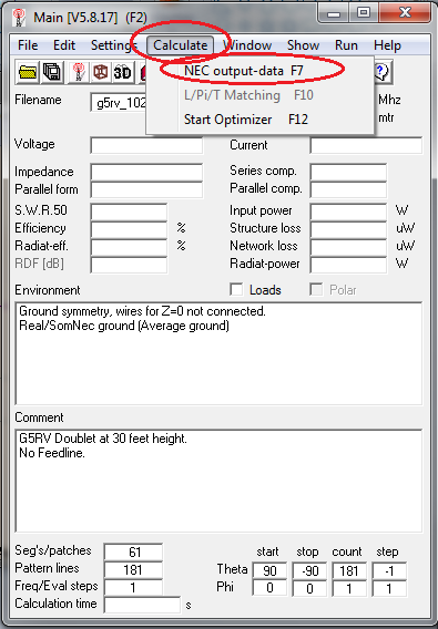
A new window should pop up.  Select "Frequency Sweep" and select the Frequency Range and Step Size (note, it seems that the maximum number of steps you can have is 512 (unless I'm doing something wrong), so pick your Step-Size accordingly).


Click on the "Generate" button.  You'll see a couple of status boxes pop up while the calculations are taking place, after which these two boxes should disappear and you should see an SWR plot and a plot of the antenna's radiation pattern.

Our goal will be the generation of the file containing the antenna's S11 S-parameters.  To do this using 4nec2, we must first create a Smith Chart from the Frequency Sweep data just generated.

To create the Smith chart, go to "Windows" on the main window and select "Smith Chart from the pull-down menu:

A Smith Chart should appear.  Go to "Export" and select "Touchstone", and then "S-par (Magn)" from the pull down menus:


You should then see a box pop up telling you that a .txt file has been created:


We need need this file to be a .S1P file.  This is as easy as changing its extension, but we first need to get to it.

On my computer, 4nec2 stores the exported .txt files in the directory C:/4nec2/plots.  Find the appropriate .txt file and change its extension from .txt to .s1p

And we now have an S1P file of the antenna's feedpoint impedance that we can use for our next step, modeling with a feedline...


Step 2:  With the S1P File, Model the Entire Antenna System and Calculate SWR and Power Loss:

We now have an S1P file of the Antenna Data's feedpoint impedance over frequency.  I will use SimSmith to model the antenna (using this file) with a ladder-line feedline.

I'll look at three different cases:

  1. Ladder-line only feedline
  2. Ladder-line plus coax feedline
  3. Ladder-line plus Balun plus coax feedline
Let's start with the first case and get SimSmith properly set up...

2.1.  Ladder-line only:

First thing to do is to launch SimSmith and select "New Circuit" under "File".

Next, let's load in the antenna's .S1P S-parameter data created with 4nec2 (enter the file's path and filename into the load's "file" box):


Now let's create the SWR plot by following the instructions in the image, below (set up the frequency range and number of points -- note that the number of points do not need to equal the number of points in the .S1P file -- SimSmith will interpolate if you've specified more).

Also, be sure to set "sweep" to "y" (i.e. yes).


Next, let's add Power Loss to the plot.  This will require that you set the generator source to "xMtch" (refer to the SimSmith manual if there is any confusion).


And below is the power-loss result.  Note that it is 0 dB (no loss).  That is because there are no lossy elements (yet) between the load and the source, and, because the source is set to "xMtch", the source is automatically matched to whatever load it sees and so there is no "mismatch" loss.


Now let's add a feedline between the load and source.  To do this, drag and drop the "feedline" block so that it's between load and source.


The resulting model should look like what you see below.  In the transmission line's parameter boxes you can select the type of transmission line (in this example I've chosen Wireman 554 Ladder-line (dry, not ice/snow).  

You can use your keyboard's up/down arrow keys to change the length of the ladder line; adjusting it until both SWR and Power-Loss meet your criteria.


Note that the G5RV model with 554 ladder-line has SWR nulls (or "almost-nulls") on 80, 40, 20, 15, and 12 meters, but not 10 meters.

If I lengthen the ladder-line to almost 40 feet, I gain 10 meters, but at a loss of 15 and 12 (by losing a band I mean that the SWR has become significantly high enough that some tuners might not be able to find a match):


Being able to change the ladder-line length in real time, and view how these changes affect SWR and loss, is a huge boon, in my opinion.


2.2.  Ladder-line plus Coax:

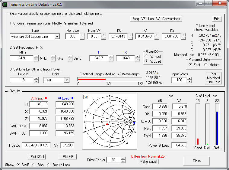
Often there might be a run of coax between the "tuned" ladder-line and the antenna tuner.  SimSmith can be used to predict how this coax will affect SWR and Power Loss.  The example below shows how a hypothetical 40 foot run for Belden 9913 coax (one of the RG-8/U variants) affects SWR and power loss.


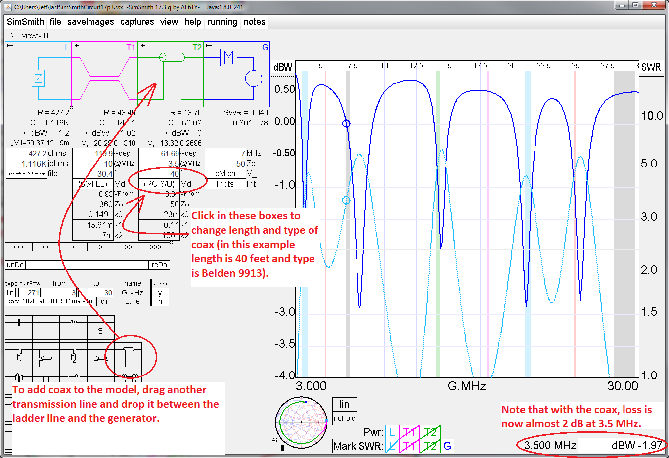
Note that SimSmith can identify Total loss as well as the loss in the coax at a user-defined frequency.  You can then derive the ladder-line loss by subtracting coax-loss from total-loss, as shown below.


.3.  Ladder-line plus Coax plus Balun:

If you want to get a general idea of how a lossless impedance-transforming balun would affect match, use SimSmith's "Transformer" block.

Below I've defined a simple impedance transformer with a 2:1 turns ratio, i.e. a 4:1 balun:  200 ohms on the left port is transformed to 50 ohms on the right port.


But an even better way to determine a balun's effect on the antenna system (including its real-world loss) is to first measure the balun's two-port S-parameters (S11, S21, S12, S22) on a Vector Network Analyzer (VNA), store them in a .S2P file, and then use this S-parameter data in the SimSmith Model's "S Block", as shown, below:


Final Thoughts...

Googling "Doublet" or "Balun" will return a plethora of hits.  Some contain good information, some contain information that is not so good.

Some claims to be wary of:

1.  Coax attached to the end of the ladder-line is part of the antenna tuning (i.e. the coax needs to be a specific length).  In fact, if the coax is 50 ohms and your transmitter wants to see 50 ohms, coax added to the end of the feedline will only "improve" the SWR because the coax is lossy and loss means less reflected power coming back to the transmitter and, thus, an "optimistically" better SWR.

The longer a run of coax is, the more loss it will have.  And the higher the SWR that this coax sees, the higher will be this loss!  Therefore, it is always best to keep any coax connections as short as possible.

2.  The ladder-line is part of the antenna's radiating system.  From the perspective of the far-field, the ladder-line should radiate only minimally, if at all.  This is because, in a balanced antenna system (which a doublet represents, having two arms of equal length and, hopefully, positioned similarly with respect to height above ground and distance from other objects), the currents at any point on the ladder-line should be equal and opposite in the ladder-line's two wires.  Thus, the magnetic fields of these currents, when viewed at a distance, should cancel.


Some Useful Web Sites:

Doublets:

Cebik, All-band Doublet

http://w4neq.com/htm/doublet.htm

W5DXP's No-tuner Doublet (Tuning is done by switching in and out different lengths of ladder line).

VK6YSF All Band Doublet (This would be an interesting antenna to simulate, given its 1:4 voltage balun and the 1:1 current balun)

ZS6BKW Doublet  (in Brian Austen's own words!  And note -- no common-mode choke between coax and ladder-line).


Baluns:

DX Engineering Balun Note


Standard Caveat:

I might have made a mistake in my designs, equations, schematics, models, etc. If anything looks confusing or wrong to you, please feel free to comment below or send me an email.

Also, I will note:

This design and any associated information is distributed in the hope that it will be useful, but WITHOUT ANY WARRANTY; without even the implied warranty of MERCHANTABILITY or FITNESS FOR A PARTICULAR PURPOSE.

Sunday, January 3, 2021

A 43 Foot Horizontal Doublet at 80 Feet

Almost six years ago I designed a 43 foot doublet that I mounted vertically for 20 through 10 meters use.

But, apart from its use in a couple of contests, it languished, and weather (or squirrels eating its ropes) eventually brought it down.

I recently became interested in the digital FT8 mode, and, in an attempt to improve my ability to make contacts on the higher bands (compared to my horizontal full-wave 80 meter loop at about 40 feet), I decided to resurrect the doublet and to mount it horizontally this time, rather than vertically.

I've described the design methodology of the vertical doublet in an earlier blog post:  k6jca 43-foot vertical doublet.  And I will recap that methodology, as well as discuss another way to approach doublet design, later in this blog post.

But first, let's get to the actual antenna itself:

A 43-foot Horizontal Doublet for 20 to 10 Meters:

From my earlier design work, I knew that I needed a long run (about 118 feet!) of Wireman 554 Ladder Line to transform the doublet's feedpoint impedance into something in the range that my tuner could match.

Given that the general rule-of-thumb for wire antennas is "the higher the better", and given the required length of the ladder-line transmission line, I needed to get the antenna as high as I could so that I wouldn't have too much excess ladder line gathered under the eaves of the house.

Using a pair of conveniently placed pine trees and my home-brew antenna launcher, I was able to raise the doublet to 80 feet above ground.  Below is a view from the ground of the doublet (wires enhanced using a Paint program).  (Other wires in the picture are part of my full-wave 80 meter horizontal loop (at a much lower height)).

Below is a side-view of the doublet.  You can see it just below the top of the picture (wires enhanced using a Paint program).  


Below are the EZNEC screenshots showing the important information.

First, EZNEC's main screen:

Note that the "Alt SWR Z0" is set to 360 ohms.  This is the approximate impedance of Wireman 554 Ladder Line (a value that is used in programs such as SimSmith and TLDetails).

And the wires defining the antenna.  Note the very short wire 2.  The source is placed at the center of this wire.

And here's a view oft the antenna:

Below are two SWR plots of the antenna's feedpoint impedance.  The first plot is for a Zo of 50 ohms.  As you can see, this would be a poor multi-band antenna if we were feeding it with 50 ohm coax.

This next SWR plot is the antenna's feedpoint impedance relative to the Zo of the 554 Ladder-Line (i.e. 360 ohms).  At first blush, still not a great multi-band antenna...


...but, with the addition of 118 feet of Wireman 554 Ladder Line, SWR (relative to 50 ohms) starts to look much better!


Note that ladder-line, although less lossy than coax, is not lossless!  The "light purple" line shows the transmission-line loss in dB.  Loss on 12 meters is approaching 2 dB.


Doublet Radiation Patterns:

For the doublet mounted at 80 feet:

20 Meters:


17 Meters:


15 Meters:

12 Meters:

10 Meters:


If you compare the "beam widths" of the Azimuth patterns for the different bands, you can see that the higher the frequency, the narrower the beam-width.  This narrowing of the beam-width may or may not be desirable, and illustrates one of the drawbacks of doublet antennas, compared to, for example, fan-dipoles -- as the azimuth beam-width narrows, the doublet becomes less useful for making contacts over a broad swath of area.


Doublet Design, Method 1:

I'll discuss two methods of doublet design.  The first method is the method I describe in my earlier blog post:  k6jca 43-foot vertical doublet

This is a multi-step method.

Step 1.  Model the antenna in EZNEC and plot SWR relative to the transmission-line's characteristic impedance (Zo).  In the case of Wireman 554 Ladder-line, this would be 360 ohms.


Step 2: (as shown in the image, above)  Pick a frequency in every ham band that you'd like the antenna to operate in and note the angle of the Reflection Coefficient (Gamma).  In the image, above, I chose 14.1 MHz for 20 meters.  And Gamma's angle at this frequency is +77.4 degrees.  (And the impedance that the Reflection Coefficient represents is 

To bring this impedance closer to 50 ohms, I will add a transmission line whose characteristic impedance is this Zo (360 ohms).  As I lengthen the transmission line from a length of 0, the Reflection Coefficient, as measured at the other end (not the antenna end) of the transmission line, can be plotted on a Smith Chart.  This value will follow a clockwise path around a "Circle of Constant SWR" as the transmission line is lengthened.  (Note, following a circle assumes the transmission line is lossless.  It isn't, but for ease of calculation I will assume that it is).

Eventually the Reflection Coefficient will rotate to intersect the x-axis on the left-hand side of the Smith Chart.  This represents the impedance value that a transmitter (or more appropriately, the antenna tuner in front of the transmitter) will see.  In this case, adding enough transmission line to rotate the reflection coefficient by 257.4 degrees (i.e. 77.4 + 180 degrees) gives us close to a 50 ohm match!

(Important note (that I will make use of): If I extend the length of the transmission line by 1/2 of a wavelength (scaled with the transmission line's Velocity Factor), I will rotate the Reflection Coefficient 360 degrees around the Circle of Constant SWR, ending back at 58.3 ohms.)

And I will calculate the amount of feedline necessary to create similar matches on the other bands.

Then, I will add successive amount of 1/2 wavelengths of line to each frequency, and tabulate the resulting lengths.  I am looking for a transmission line length that is common (or close to common) on all bands of interest.

I wrote a spreadsheet to do this calculation for me.  You can see that a feedline length of around 118 feet rotates the reflection coefficients for all bands around the Smith Chart to give a fairly good match (the green boxes in the table, below):


Notes on the above spreadsheet:
  1. The values in the "Transmission Line, Half wavelength (feet)" cells equal c*Vf/(2*frequency), where c is the speed of light in feet/sec, Vf is the transmission line's velocity factor (0.93 for 554 ladder line), and frequency is in Hz.  Note that this is the length of transmission line required to rotate 360 degrees around the Smith Chart. For 14.1 MHz and 554 Ladder Line, this length calculates to be 32.45 feet.
  2. The "Length to First Minimum Z (feet)" is amount of rotation required to rotate the Reflection Coefficient clockwise to lie on the x-axis on the left-hand side of the Smith Chart.  This angle will be less than 360 degrees, and thus the length will be less than the "half wavelength" calculated length (see above).  In the example of 14.1 MHz, this value equals ((77.4 degrees + 180 degrees)/360 degrees)*(32.45 feet), where 32.45 feet is the length of transmission line that will rotate the Reflection Coefficient 360 degrees around the Smith Chart.
  3. The "Length to Next Zmin (feet)" cells simply add an additional half-wavelength of transmission line each time.  In other words, rotating 360 degrees around the Smith Chart each time.

Calculating Transmission Line Power Loss:

Part of a design should include estimating power loss in the transmission line.  If I know the antenna's feedpoint impedance (from the EZNEC SWR plot), the type of transmission line (e.g. Wireman 554 Ladder Line), and the length of the transmission line, I can use AC6LA's "Transmission Line Details" (TLDetails) program to calculate power loss.

Below are the calculations for each band:

20 meters (ladder-line loss 0.715 dB):


17 Meters (ladder-line loss 1.164 dB):


15 Meters (ladder-line loss 1.551 dB):


12 Meters (ladder-line loss 1.896 dB):


10 Meters (ladder-line loss 1.833 dB):


Of course, this is only the loss calculated at one frequency in each band.  Power-loss will vary across a band as SWR varies.  But this value gives you an idea of how much loss there can be, even in "low-loss" ladder-line.

Also, as an interesting point, note that the True Zo of Wireman 554 Ladder Line is slightly complex, not real, and equals 360.466 - j0.443 ohms (see lower left-hand side text box).


Doublet Design, Method 2:

Design method 2, discussed above, requires a number of separate steps and it involves writing down intermediary values to be input later into other programs (such as antenna feedpoint impedance, from EZNEC, into the Transmission Line Details program).

It also relies on assumptions, such as the transmission line being lossless, for my Excel Spreadsheet.

And, power dissipation is calculated at a single point in a band.  Calculating additional points is additional work.

Design Method 2 simplifies the process and gives more information (e.g. power loss across a range of frequencies).

The first step requires creating a "Touchstone"-compatible file of the antenna's S11 values (this would be in the form of an .s1p file).

Although there are versions of EZNEC which can generate s1p files, the version I own is not one of those.

So, instead, I use the free antenna-modeling program "4nec2" to create the s1p file.  Unfortunately, this is not as easy as simply creating an antenna model and clicking a button.  4nec2 requires that you first calculate the NEC output-data as a frequency sweep.  Then you need to open a Smith Chart window, and then, from this Smith Chart window you need to export the Smith Chart data as a Touchstone file (you have four formatting choices, I use "s-par (Magn)" (i.e. s-parameters, magnitude (and angle)).  


But wait, you still aren't done.  The Touchstone file is written as a .txt file.  You need to find this file and rename its extension from .txt to .s1p.  (Note that on my computer, 4nec2 always writes this file to the folder:  C:/4nec2/plots).

When the .s1p file has been created containing the antenna's S11 data, you can load it into SimSmith and then model how a transmission line can bring your antenna's impedance down to an acceptable SWR (that a tuner can match), as well as calculate how much power will be lost in the transmission line.  The SimSmith screen-capture below shows how this is done:


Notes:
  • SimSmith really simplifies finding an appropriate length of feedline (no EXCEL spreadsheet required!).  Simply insert a transmission line between the load (defined by the antenna's s1p file) and source, select the type of transmission line (e.g. 554, dry conditions), and then increment the length of the line up or down while watching the SWR nulls move with respect to frequency on the SWR plot (I use my keyboard's up/down arrows to do the incrementing).  When they look good, note the transmission line's length!
  • You can also plot transmission line power-loss across the frequency range.  Simply set SimSmith's Generator Model to xMtch (as shown, above).  This will define a generator that is a perfect match for the impedance it sees (thus removing loss due to mismatch), so that any losses in the network between source and load are due solely to the network itself (in this case, the network being the transmission line).  You can see loss plotted, above (light purple dotted line).

Adding Additional Coax to the Transmission Line:

At my QTH I need to bring the transmission line in through the side of the house and then to my operating position.  Rather than run ladder-line through the wall, I run a 20 foot piece of RG-142/B coax from my operating position, through the wall, and out to the eaves of the house, where the coax connects to the ladder-line.

This coax will add additional loss which we can calculate using SimSmith.  Below is the model including 30 feet of RG-142/B:


Loss through both transmission lines totals to be 1.43 dB.  Of this value, there is a loss of 0.716 dB in the coax, leaving the reminder of the loss (0.714 dB) as ladder-line loss.  (Note that the value of the transmission line loss (0.714 dB) is essentially identical to the loss calculated earlier (in Method 1) using the "Transmission Line Details" program (in that case, the loss was 0.715 dB).

And note how the coax causes the loss to be significantly worse as we move away from minimum-SWR on the higher frequencies.


Measured S11:

Below is an S11 measurement of the Doublet antenna at the transmitter-end of the run of RG-142/B coax (30 feet?) that connects the end of the ladder-line transmission line to my transmitter.  VNA is an HP 3577A.


Comparing Measured S11 versus SimSmith Simulation:

Below is a plot comparing the measured SWR of the Doublet antenna system (calculated from the S11 data captured by the HP 3577A VNA) to the SimSmith Simulation of a 43 foot doublet fed with 118 feet of Wireman 554 Ladder-line and 30 feet of RG-142B/U.


As you can see, the two are quite close, despite there being some amount of uncertainty as to the actual wire lengths that I cut for the doublet as well as the lengths of ladder-line and coax (although coax length ought not change the position, with respect to frequency, of the SWR nulls).


Standard Caveat:
I might have made a mistake in my designs, equations, schematics, models, etc. If anything looks confusing or wrong to you, please feel free to comment below or send me an email.

Also, I will note:

This design and any associated information is distributed in the hope that it will be useful, but WITHOUT ANY WARRANTY; without even the implied warranty of MERCHANTABILITY or FITNESS FOR A PARTICULAR PURPOSE.