
The ME-165/G is a military SWR and Power meter, designed for the HF
bands (1.5 - 30 MHz), that includes an internal 600 watt dummy load.
The
image, below, shows the ME-165/G as part of the AN/GRC-26D shelter-mounted
radio teletype station:

The unit provides a convenient way to switch the dummy load in and out
of the transmission line, plus, if tuning an antenna tuner in SWR mode, its
SWR circuitry allows the transmitter to always see a 50 ohm load, irrespective
of the actual load at the unit's Output port. So you don't need to worry
about destroying your finals if you make a mistake while tuning your antenna
tuner.
There are four modes of operation (per the four positions of
the front panel's rotary switch). The table below describes how the
ports connect and the meter function for each of these four modes:

The following illustration shows this same information as a "functional
diagram" (i.e. part block diagram, part schematic).

Antenna Tuning Procedure:
When tuning an antenna tuner, the ME-165/G should first be placed
into "ADJUST" mode and the "ADJUST" potentiometer rotated for a full-scale
meter reading while transmitting a CW signal.
Then turn the rotary
switch to its "SWR" position and adjust an external antenna tuner (connected
between the ME165/G's Output connector and the antenna) to give a minimum
reading on the SWR meter (for a correctly tuned tuner, the meter's needle
should end up in the green-region at the left-hand side of the scale).
Here
is a closeup of the Power and SWR meter scales:

Note that the SWR scale is NOT accurate above about 2:1. (I'll
discuss this in more detail later in this blog post).
Schematic:
The schematic, from the Army's Technical Manual. I've corrected a couple of errors (my corrections are in
red):

Also, note that C8 (the capacitor at the Input connector) is listed in
the schematic as 40 pF. In the two ME-165/G units that I have, its
capacitance is actually 39 pF.
Schematic Notes:
1. The 1200 ohm, 25 watt resistor, R15 in the schematic, in
series with the SWR Bridge circuit reduces the power delivered to the SWR
bridge circuit (therefore, the bridge can use 1/2 watt resistors).
2.
SWR Detection is via a Wheatstone bridge. The bridge is balanced when
the load at the ME-165/G's Output port is 51 ohms.
3. C6 puts
the ADJUST pot wiper at RF Ground, thus R22 (1200 ohm) is essentially in
parallel with the lower-right-hand side side of the bridge (via
C5) -- i.e. this resistance is in parallel with whatever load
is attached to the unit's Output port.
Thus, an equivalent
resistance (R20, 1200 ohms) must be connected in parallel with the
lower-left-hand arm of the bridge to ensure that the bridge is balanced
when the external antenna impedance connected at the Output side of the bridge
is 51 ohms, resistive.
ME-165/G Performance:
I own three ME-165/G's. Let's look at their performance.
First,
the unit manufactured by Radalab, Inc:
The (first) Radalab, Inc., ME-165/G (circa 1970's):
I picked up this unit many years ago. The unit was in good
shape, but a previous owner had replaced the original N connectors with SO-239
connectors.

Inside, the majority of the components are wired point-to-point using
solder posts:

Below is a photo showing the wiring from one side of the Dummy Load to
the rotary switch and from the other side of the Dummy Load to ground.
Note that the load's ground wire goes to C8's ground terminal. This
terminal is then grounded to the front panel via a separate wire.
The
other wire from the load (to the rotary switch) is bound tightly with the
ground wire from the load, using three cable ties.

The 50 ohm, 600 watt load consists of twelve Dale 600 ohm, 50 watt
resistors in parallel:

S-Parameters:
Measuring the unit's S-Parameters
in dummy-load mode with an HP 8753C Network Analyzer:

Below is the capture of S11 when the ME-165/G's rotary switch is set to
POWER (i.e. the Input port is connected to the 50 ohm Dummy Load). You
can see that the SWR in the HF band (to 30 MHz) looks very good (1.1:1 at 30
MHz). Not so good at 6 meters, but this load is not spec'd to that
frequency.

When the front-panel rotary switch is in the OPERATE position, the dummy
load is disconnected from the Input connector and the Input is connected
directly to the Output connector.
How does the Radalab ME-165/G
affect performance when it is in its OPERATE mode? Again, let's look at
the s-parameter measurements...
As you can see in the plot below,
there is some insertion loss that worsens with frequency, but this loss is
only about 0.09 dB, worst case, at 30 MHz.

And the SWR of the "ideal" 50 ohm external load, rather than being 1:1,
is now changed by the Radalab ME-165/G to be 1.2:1 (at 30 MHz).

So, some minor adverse effects, but overall, not bad!
Improving the performance of this (first) Radalab ME-165/G in OPERATE
mode:
I had noticed a difference between the Oneida's output wiring and
the wiring of the Radalab unit, and I wondered if this difference accounted
for the slightly worse Radalab Insertion Loss when in OPERATE mode.
The
wiring from the rotary switch to the Oneida unit's output connector had been
routed next to the front panel. But the same wire in the Radalab unit
was routed high in the air, as shown below:

Would moving this output wire to be closer to the front panel make a
difference? Here's a photo of the new routing:

And below is the measured s-parameters for this new routing. Note
that Insertion loss has decreased from 0.09 dB to about 0.07 dB. Note
much of a change, but it's in the right direction.

And the image below shows that the SWR of the "ideal" 50 ohm load is now
1.1:1 (from 1.2:1). Again, a slight improvement, but an improvement
never-the-less.

Oneida Electronics Inc ME-165/G (circa 1963):
My second ME-165/G was manufactured by Oneida Electronics Inc,
around 1963 (per the suffix on the Order Number listed on the front panel
tag).
This unit still has the stock N-connectors on the front panel
(note that in the image, below, there are BNC adapters attached).

Here's a look at the inside terminal-board used for wiring the
components. You can see that it is similar to the later Radalab's board
(shown above):

But there is one noticeable difference between the Radalab board and the
Oneida board, which is the use of clips to hold in CR1 and CR2, rather than
soldering them to posts, as shown in the two photos, below:


I imagine clips allowed easy replacement of the original 1N69A diodes in
case they blew out. Note that CR2 (a 1N277 diode) has its leads wrapped
around the clip's posts. This diode probably replaced a bad 1N69A
diode.
The image below shows Oneida's wiring from the 600 watt
dummy load to the rotary switch and ground. Note the difference between
this wiring and the wiring in my Radalab unit (shown earlier in this
post). The wires below are not routed together in
parallel, and the dummy load's ground wire goes directly to a ground terminal
on the front panel, rather than first routing to C8's ground.

Also, the dummy load's resistors are not Dale resistors; instead they
are TRU-OHM 600 ohm non-inductive resistors:

Improving the performance of the Oneida ME-165/G:
When I first measured the SWR of the dummy load, I noticed that
it rose to 1.5:1 at 30 MHz. So I tried to improve its SWR by changing
the dummy load's wiring to look exactly like the wiring in my Radalab
ME-165/G.
But with this modification the SWR rose to 1.75:1
at 30 MHz (see below). Yikes -- my attempt to make the Oneida's wiring
match the Radalab wiring moved SWR in the wrong direction!

OK -- mimicking the Radalab's wiring was not going to work.
Playing around with the separation of the dummy load's two wires, I discovered
that (a) separating the two wires far apart, and (b) keeping the
original ground wire to the dummy load, in addition to the new (red)
ground wire I'd added, improved the SWR.
The image below shows the
new dummy-load wiring. The red wires are 14 AWG THHN stranded wires
(insulation rated to 600V). Note their separation! You can see the dummy
load's grounding red wire goes to C8, just like the wiring in the Radalab
unit. But you can also see that the original ground wire is still
connected to the dummy load (and now routed a bit closer to the upright
mounting plate).

And here is the new SWR measurement. Now it is 1.2:1 at 30 MHz.

(Perhaps the difference in wiring is due to a difference in impedance
between the Oneida's 600 ohm TRU-OHM resistors and the Dale 600 ohm resistors
in the Radalab unit?)
In OPERATE mode the Oneida unit's
measurements look very good. Here's S21. Insertion loss is only
about 0.04 dB at 30 MHz.

And there is little impact on the SWR of an external 50 ohm load.
As you can see, below, the SWR at 30 MHz for the external 50 ohm load is
1.09:1.

Second Radalab, Inc., ME-165/G (S/N 47C):
The first Radalab unit I discussed (above) is serial number
7C. This second ME-165/G is serial number 47C.
Interestingly,
its component-mounting board no longer has the clips for the diode
leads. Instead, all components are attached with soldering posts:

(This difference could be due to a later unit upgrade, or it might have
been a change during the manufacturing run).
Otherwise, the two
Radalab units look very similar.
S-Parameters:
Again, made with my HP 8753C Vector Network Analyzer.
Below
is the S11 plot with the Function Switch set to POWER. Note that the SWR
at 30 MHz is about 1.5:1. Not as good as I would like it to be.

Below are the s-parameters with the Function Switch set to OPERATE:

SWR (of an external 50 ohm load) is transformed to about 1.3:1 (from the
load's original 1:1) at 30 MHz.
And Insertion Loss is about 0.1
dB.
Improving the performance of this second Radalab ME-165/G:
The image below shows the original wiring of this ME-165/G:

If I routed the dummy-load wires together (using tie-wraps), SWR in
POWER mode improved.
The image below shows the new routing of the
two dummy-load wires:

(Note, I had to trim off a small amount of the wire going to the big
black cap because it was just a too long, as you can see in the photo,
below.)

With this modification, the dummy-load's SWR went from 1.5:1 to less
than 1.1:1 (see below).

I had noted that the wire to the output jack was up in the air. So
I moved it to route along the inside of the front panel.
I don't
know the voltage rating of this wire's insulation, and I was a concerned that
it now ran against the grounded metal of the front panel, so to prevent the
possibility of arcing I added a bit of Kapton tape between it and the panel
for extra voltage insulation (and I added a second piece of tape to hold the
wire next to the panel), as shown below:

This modification improved OPERATE mode's Insertion Loss (from 0.1 dB to
about 0.05 dB) and the "through" SWR of an external 50 ohm load (now 1.1:1
from the unmodified version's 1.3:1).

An SWR Meter that does not measure SWR:
While using the ME-165/G, I discovered that its SWR
readings can be very inaccurate'
Here's a look at the SWR scale on
the ME-165/G meter.

As I mentioned, the SWR reading can sometimes by quite inaccurate.
For example, what should be the SWR when the load is a short? Of course,
it should be infinite (meter needle at full scale). But
that's not what the ME-165/G shows:

So my Radalab unit shows that the SWR of a short-circuit is somewhere
between 3:1 and 4:1. And if I repeat the test on my Oneida unit, the SWR
of a short measures slightly less than 3:1 (the difference between the two is
probably due to drift of component values over time).
In other
words, both of my ME165/G SWR meters show an SWR of around 3:1 for a short
circuit. Neither unit shows the correct SWR of infinity
(meter needle at full scale).
Despite this gross SWR inaccuracy for
a short-circuit load, the SWR meter's accuracy seems to improve considerably
below an SWR of about 2:1. Therefore, as long as the goal is
to tune the antenna for minimum SWR, rather
than measure its SWR value, the ME-165/G does the job quite
well.
But I still wanted to know -- why was the SWR meter so
inaccurate for a short-circuit load?
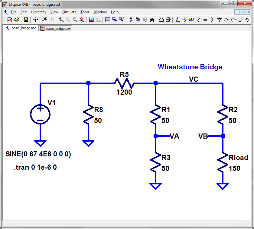
SPICE Simulations:
I decided to do some SPICE simulations to get a better
understanding of what to expect from the ME-165/G SWR detector.
The
ME-165/G's SWR measurement circuit is based upon a simple Wheatstone Bridge,
with the unknown load to be measured represented by the lower right-hand arm
of the bridge, as shown, below:
In an ideal Wheatstone Bridge we can take the difference between Va and
Vb, then divide by Va, and then take the magnitude of this
value, we can create a set of numbers that we can equate to SWR values, as
shown in the table, below:

Note that the quantity |(Va - Vb)/Va| is equivalent to the magnitude of
the load's Gamma:
In other words, if we could measure Va and Vb with high impedance measuring
circuits (so that there are no unwanted currents through either arm of the
bridge that might alter the bridge's balance) and then perform the math, we'd
get a number equal to the magnitude of the load's Gamma, and thus translatable
to its SWR.
Sounds straightforward, but note...the equation
requires a division by Va. Is there an easy way to accomplish this
division with simple circuitry?
If we could adjust our voltages so
that Va equals 1 (while keeping the ratio of Va to Vb constant), then we can
skip the division step, because we would be dividing by 1.
In the
bridge circuit above, for example, maybe we would have a switch that we would
first set to an "Adjust" position, connecting a high-impedance meter to Va and
letting us scale its gain (via a potentiometer) until the meter's needle is at
Full Scale, i.e. so that Va now equals 1.
And then we would flip
the switch to measure |Va - Vb|, using the same gain-adjusted high-impedance
meter, to give us a direct reading of Gamma thus SWR (e.g. a meter
reading of 1/2 Full Scale would equal a Gamma of 0.5, or an SWR of 3:1).
But
we can see from the SWR scale on the ME-165/G meter, and from our example
measuring the SWR of a 0 ohm load, that the ME-165/G is doing something very
different -- something that affects the accuracy of its SWR readings.
The
problem is that, for the equation Vswr = |(Va-Vb)/Va| to give accurate
results, Va must be measured while Rload is connected to the
Wheatstone Bridge. This is because, given the ME-165's circuitry to limit the
power to the Wheatstone Bridge (i.e. the series 1200 ohm, 25 watt resistor ),
any change in Rload will affect the voltage at node Vc at the top of the
bridge (because a change in Rload will change the current through that arm of
the bridge, and thus it changes the current (and subsequent voltage drop)
through this series 1200 ohm resistor feeding the bridge).
Because
we are adjusting Va to be 1 (to avoid a mathematical division), the value of
Va that was set during the "Adjust" step should (ideally) be the same as the
value of Va used during the SWR measurement step.
But in the
ME-165/G, these two Va's are not the same. The Va of
the Adjust step is measured without Rload connected to the
bridge, while Va of the SWR measurement step is
measured with Rload connected to the bridge.
So Vc
will be different for these two steps, and thus Va (which equals Vc/2) will
also be different.
Let Va1 be the value of Va measured during the
Adjust, and "Va2" be the value of Va measured during the SWR measurement
step. Because the "Adjust" step is, essentially, determining the value
of Va that we will use to normalize the quantity (Va2 - Vb), the original
equation |(Va - Vb)/Va| becomes:
Vswr = | (Va2 - Vb) /
Va1 |
I can simulate the result in LTSpice by adding another arm to
represent the "unloaded" Va (i.e. Va1). Below is the model, and I've
annotated it with the simulation results of this new equation.

We can see that the measured SWR values are different
for loads with the same actual SWR (e.g. 0.34 for 150 ohms
versus 0.21 16.67 ohms -- both loads have an actual SWR of
3:1), and it explains why the ME165/G's measured SWR of a short is so far off
from what it should be.
Let's now add the diode detector and
meter circuit to the simulation and see how they affect performance.
Please note:
1. LTSpice doesn't seem to have any Germanium diode models, so I'm using a Schottky diode (1N5817), instead. (Note: if replacing the original CR1 or CR2, I'd recommend using a 1N5818 or 1N5819 for their higher peak-reverse-voltage specifications.)
2. I've adjusted the amplitude of the driving voltage source so that R23 (representing the "Adjust" potentiometer) is 0 ohms and the meter current is 1.0 mA when Rload = 1 Megohm (by setting the current equal to 1 mA for Rload = 1 Meg, I am effectively mimicking the "Adjust" step of the SWR measurement).
3. The 1 mA meter is represented by Rmeter (58 ohms), per my measurement of the meter's resistance. And I've increased the meter's bypass cap (C7) from 1 nF to 100 nF to knock down the RF across the meter and make it easier to determine the DC current passing through Rmeter.
4. The frequency of the sine-wave drive is 4 MHz.
5. Circuit parasitic elements are not included in the simulation.
I would expect the addition of the diode-detector to throw off the simulated
values determined earlier (for the "ideal" Wheatstone Bridge), because the
diode will conduct during part of the RF cycle, squirting current from the
right arm of the Wheatstone Bridge (Vb) into the left arm (Va) and thus
changing these two voltages.
Here's the new LTSpice schematic:

And below are some simulations of this new circuit...
First,
verifying that the "meter" current is 1 mA when mimicking the ME-165/G in
ADJUST mode, i.e. when there is no load (Rload = 1 Megohm):

Next, replacing the "open" load with a short. Ideally, the current
should remain 1 mA (representing an infinite SWR). But as you can see,
the DC current is 0.4 amps, which is quite a ways off from the 1 mA target.

Let's take a look at two loads that should each have an SWR of 3:1:
First,
a Load = 150 ohms (note that the meter current is 0.32 mA):

Next, a Load = 16.67 ohms (note that the meter current is 0.21 mA):

These results are not exactly the same as the results made without the
actual diode-detector in the circuit, but they are close. (I believe the
difference is due to the actual diode-detector acting as a current path
between the two arms of the bridge, when in fact these two arms should be
isolated from each other).
Below is a table of simulation results,
simulated at 4 MHz and at 10 MHz, for different load resistances. The
third column is the actual DC current required to drive the meter's needle to
the appropriate "tick" mark on the ME-165/G meter's SWR scale. If you
compare the "required" current to the "actual" (i.e. simulation) current, you
can see that only some of the simulated currents come close to target
values. Only when the load's actual SWR is about 2:1 or better do we
seem to get in the ballpark of the actual meter tick marks, irrespective of
whether the load is greater than 50 ohms, or less than 50 ohms.

The simulated results also depend upon the type of diode
used. As I mentioned earlier, LTSpice does not seem to have a Germanium
diode model, so I used a 1N5817 Schottky diode instead.
I thought
I'd look at the simulation results using other LTSpice diode models. The
table below shows simulation results of two different Schottky diodes (1N5817
and BAT54), and a common 1N4148 Silicon diode.

Note the loss of resolution at low SWRs if using the 1N4148 diode.
This will result in tuning appearing to give a 1:1 SWR over a broader range of
loads, which is not desired!
Conclusions:
1. The ME-165/G provides a 600 watt dummy-load and
power-measurement meter for the HF range of 1 to 30 MHz) that can be easily
switched in and out of the transmission line.
2. It might be
possible to improve either the dummy-load's SWR or the "through" insertion
loss at the high end of the HF range by changing wire routing. Use a
Vector Network Analyzer (such as the NanoVNA) to accomplish this by measuring S21 and S11.
3. The
ME-165/G provides an SWR measurement mode useful for adjusting antenna
tuners. However, the meter's accuracy very much depends upon the load
value. Accuracy seems to improve as the SWR drops below 2:1.
4.
If replacing diode CR2 in the SWR circuit and you cannot find the original
1N69A (or 1N277), try using a Schottky diode such as a 1N5818 or 1N5819,
rather than a generic silicon diode such as the 1N4148. (On the other
hand, a 1N4148 diode should be fine as a substitution for CR1).
I
recommend the 1N5818 or 1N5819 instead of the 1N5817 I used in my simulations
because these two diodes have a higher peak-reverse-voltage specification
compared to the 1N5817. Although PRV of the 1N5817 is 20 volts and the
worst-case simulated peak-reverse-voltage was around 14 volts (for Vin =
250Vpp, F = 2 MHz, Rload = Open, and the bridge resistors assuming a worst
case 10% variation (R19 = 56 ohms, R21 = 46 ohms, and R18 = 46 ohms)), I
personally would prefer to have a bit more PRV margin.
Resources:
Technical Manual TM 11-6625-333-15
PA0FRI ME-165/G website
Standard Caveat:
I might have made a mistake in my designs, schematics, equations,
models, etc. If anything looks confusing or wrong to you, please feel
free to leave a comment or send me an email.
Also, I will note:
This
design and any associated information is distributed in the hope that it will
be useful, but WITHOUT ANY WARRANTY; without an implied warranty of
MERCHANTABILITY or FITNESS FOR A PARTICULAR PURPOSE.


