I was recently comparing measurements of a common-mode choke's impedance (measured several different ways using a Vector Network Analyzer -- see here). Unfortunately, each method I used gave different results, such as the two measurements shown in the image, below (one impedance derived from an S11 measurement, and the other derived from S21):

For comparison purposes, I thought it would be useful to calculate what the impedance ought to be, given the toroid core geometry and the ferrite mix. (In this example, the core is a Mix 31 FT-240 core.)
But how to do this?
Fortunately, the Fair-Rite website has a number of resources, such as a paper titled "Specifying a Ferrite for EMI Suppression," by Carole U. Parker. This paper has all of the information required to express the equation for inductance given a ferrite toroidal inductor (e.g. the paper's equation 9 and the definition of L0 at the back of the paper).
The site also has downloadable .CSV files containing the "relative permeability" data, versus frequency, for various ferrite mixes.
In other words, everything I needed was there.
To tie it all together I wrote a MATLAB script to read the relative-permeability .csv file for a particular mix and, given the ferrite core's dimensions, calculate and then plot impedance as magnitude and phase as well as resistance and reactance versus frequency.
But first, some theoretical background:
The basic formula for a toroidal inductor is:
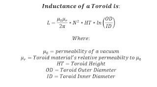
The Fair-Rite paper uses log10 rather than natural log in its equation for inductance. I would like to use this convention so that I can check my final derivation against Fair-Rite's formulas. So, including this conversion, plus converting permeability to H/mm (because the core dimensions are given by Fair-Rite in mm), I can express my final equation for inductance, as shown, below.


The inductance equation, above, represents a complex inductance consisting of both real and imaginary parts.
The impedance of this inductor can be calculated by multiplying inductance by jω. Note that ω (in radians/sec) can be replaced by 2π*frequency (where frequency is in Hz).
The resulting impedance equation is shown, below. I've also expanded the equation to show the series resistance and reactance components of this impedance.

(Note that u'', the relative-permeability's imaginary component, determines the inductor's resistive losses, while u', the relative-permeability's real component, determines the inductor's reactance.)

Taking into account this parasitic capacitance, the actual impedance of the ferrite toroidal inductor is the calculated complex impedance of the inductor in parallel with the shunt capacitor's impedance:

If using MATLAB and its matrix-based math to calculate the actual impedance versus frequency, it is convenient to first convert impedance to admittance, sum these, and then convert the sum back to the actual impedance (matrix) of the device:

% Calculating Impedance of an Inductor wound on a Ferrite Toroid core.
% Date: 220209
% k6jca
%
% Inductance is calculated using a formula derived from equations in the
% paper: "Specifying a Ferrite for EMI Suppression," by Carole U. Parker
% of Fair-Rite Products.  This paper appeared in the June, 2008 issue of
% "Conformity", but should be found on the Fair-Rite site (Google title).
%
% Self-Resonant-Frequency (SRF) is simulated by specifying a shunt
% capacitance value paralleled with the inductor.
%
% The ferrite mix's u' and u'' values (vs frequency) come from a .CSV file
% downloaded from the Fair-Rite website.
%
% The inductor analyzed in this example is 12 turns wound on a Mix 31
% FT-240 core.
%
% Run on MATLAB Version R2020a


clear;
clc;
close all;

comment1='12 tight turns on FT-240 Mix 31 Core';  % for Plot annotation

% The ferrite mix u' and u'' data is in the following .CSV file.  Note that
% the data in Fair-rite's downloadable .CSV file spans the frequency range
% of 10 KHz to 1 GHz (much more than I need), and so I trimmed it down
% to cover only 1-60 MHz and renamed the file:
ftoread = '31-Material-Fair-Rite_1MHz-60MHz.csv'; % File with Mix data

N = 12;  % inductor's number of turns

% FT240 dimensions
OD = 61;    % outer-diameter, in mm
ID = 35.55; % inner-diameter, in mm
HT = 12.7;  % height, in mm

% Define the inductor's shunt capacitance (which affect the inductor's
% self-resonant-frequency (SRF).
% (One can manually adjust so that calculated SRF is similar to
% measured SRF).
Cp = 0.65e-12;               % in Farads
Cp_text = num2str(Cp*1e12);  % For plot annotation

% Read Fair-Rite's "mix" data from the CSV file and store in matrices.
% Note that the Excel file is in a directory parallel with the directory
% holding this matlab script.
A = readmatrix(['..\Excel\',ftoread]);  % CSV file is in EXCEL directory
f = A(:,1);      % frequency
u1 = A(:,2);     % Ferrite's u' value
u2 = A(:,3);     % Ferrite's u'' value

jw = 1i*2*pi*f;  % convert frequency to radians

% Calculate the inductor's impedance.
% (Formula derived from equations in the paper: "Specifying a Ferrite
%  for EMI Suppression," by Carole U. Parker of Fair-Rite Products.)
Zl = jw*4.6052e-10*(N^2).*(u1-1i*u2)*HT*log10(OD/ID);

% The shunt capacitance is in parallel with the inductor, and is
% the source of the inductor's Self-Resonant-Frequency.
%
% Because it is in parallel, a simple way to calculate its effect
% on impedance is to convert the inductor's and capacitor's impedances
% to admittances (admittance is just the inverse of impedance), add them,
% and then convert the sum back to impedance.
% MATLAB's 'RF Toolbox' has two nice routines for doing the matrix
% inversions: z2y() and y2z().
%
YZl = squeeze(z2y(Zl));         % inductor's admittance
YCp = (jw*Cp);                  % capacitor's admittance
Yactual = YZl + YCp;            % sum admittances
Zactual = squeeze(y2z(Yactual));% Final impedance (Z(inductor) paralleled
                                % with Z(cap)) is the inversion of Y
The MATLAB script can be downloaded from the following github directory:
https://github.com/k6jca/Calculating_Ferrite_Toroid_Inductor_Impedance
Note that the script in the directory contains the MATLAB code, above, plus code (not shown above) to generate the plot, below.
I ran my code using MATLAB revision R2020a, but you will need at least MATLAB revision R2019a (it's required for the readmatrix() function). Of course, you can always use an earlier version, but you'll need to replace readmatrix() with something else.
The same caution applies to the sgtitle() function. This function first appears in MATLAB revision R2018b.
Impedance of 12 turns on a Mix 31 FT-240 Ferrite Core:
Below are curves shown the calculated impedance of an inductor created by winding 12 turns around a Mix 31 FT-240 core. Impedance is shown in terms of Magnitude and Phase, and also in terms of series Resistance and Reactance.
The shunt capacitance was set to a value of 0.65 pF. (The next section explains why 0.65 pF was chosen.)

Selecting a Shunt Capacitance value:
Why choose 0.65 pF? Why use any capacitance?
If there were no shunt capacitor (i.e. its capacitance = 0 pF), then there is no self-resonant point for this inductor (at least out to 60 MHz) -- the inductor remains inductive over the frequency range of 1 to 60 MHz:

But measurements made with a VNA exhibit a resonance.
And so I chose a shunt capacitor value (in this case 0.65 pF) that makes the resonant frequency of the ferrite inductor's calculated impedance the same as the resonant frequency of the Y21-derived impedance (derived from the VNA measurements), as shown below (i.e. both the calculated phase and the impedance-from-Y21 phase cross 0 degrees at the same frequency).

As you can see, the calculated impedance, although not exactly the same as the impedance found via the Y21 method, is in the ballpark. Differences between calculated and measured impedances could be caused by any of a number of factors -- dimensional variations in core size, mix variations, actual winding style vs. ideal winding style, measurement error, etc.
(Note: also shown is the impedance measured using S11, which I consider to be an inferior method of measuring common-mode choke impedance.)
Conclusions and Notes:
1. I consider the Y21 method of measuring a common-mode choke's impedance to be superior to the G3TXQ method of using only a VNA's S21 measurement, but, in the range of 1 to 30 MHz, the difference is not that significant (in my experience).
2. The value of the parallel parasitic capacitance is a subjective choice. I chose a value to make the resonant frequency of the calculated impedance the same as the resonant frequency of the Y21-derived impedance. But is this the best choice? I do not know.
3. If a multi-pole RLC ladder-network model is synthesized from the measured impedance (i.e. the Y21-derived impedance), and the capacitance of this synthesized model compared to the shunt capacitance I added to the Fair-Rite calculated inductance, the values are quite close (i.e. 0.62 pF for the synthesized model versus 0.65 pF for the Fair-Rite calculated Z).
The synthesized RLC ladder-network, created by Dick Benson, W1QG, using a custom MATLAB tool that will synthesize a network from the S-parameter measurements of an inductor (e.g. my VNA measurements for the 12-turns on the Mix 31 FT-240 core), looks like this:

You can see that the derived capacitance is 0.62 pF. Quite close to the 0.65 pF I chose for the Fair-Rite derived model.

My Balun (and 80-Meter Loop) posts:
A 3-Port Method for Characterizing Baluns: http://k6jca.blogspot.com/2020/06/another-method-to-characterize-baluns.html
I might have made a mistake in my designs, equations, schematics, models,
etc. If anything looks confusing or wrong to you, please feel free to
comment below or send me an email.
Also, I will note:
This
design and any associated information is distributed in the hope that it
will be useful, but WITHOUT ANY WARRANTY; without even the implied warranty
of MERCHANTABILITY or FITNESS FOR A PARTICULAR PURPOSE.


