Almost six years ago I designed a 43 foot doublet that I mounted vertically for 20 through 10 meters use.
But, apart from its use in a couple of contests, it languished, and weather (or squirrels eating its ropes) eventually brought it down.
I recently became interested in the digital FT8 mode, and, in an attempt to improve my ability to make contacts on the higher bands (compared to my horizontal full-wave 80 meter loop at about 40 feet), I decided to resurrect the doublet and to mount it horizontally this time, rather than vertically.
I've described the design methodology of the vertical doublet in an earlier blog post: k6jca 43-foot vertical doublet. And I will recap that methodology, as well as discuss another way to approach doublet design, later in this blog post.
But first, let's get to the actual antenna itself:
A 43-foot Horizontal Doublet for 20 to 10 Meters:
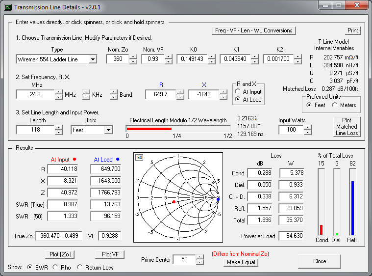
From my earlier design work, I knew that I needed a long run (about 118 feet!) of Wireman 554 Ladder Line to transform the doublet's feedpoint impedance into something in the range that my tuner could match.
Given that the general rule-of-thumb for wire antennas is "the higher the better", and given the required length of the ladder-line transmission line, I needed to get the antenna as high as I could so that I wouldn't have too much excess ladder line gathered under the eaves of the house.
Using a pair of conveniently placed pine trees and my home-brew antenna launcher, I was able to raise the doublet to 80 feet above ground. Below is a view from the ground of the doublet (wires enhanced using a Paint program). (Other wires in the picture are part of my full-wave 80 meter horizontal loop (at a much lower height)).

Below is a side-view of the doublet. You can see it just below the top of the picture (wires enhanced using a Paint program).

Below are the EZNEC screenshots showing the important information.
First, EZNEC's main screen:

Note that the "Alt SWR Z0" is set to 360 ohms. This is the approximate impedance of Wireman 554 Ladder Line (a value that is used in programs such as SimSmith and TLDetails).
And the wires defining the antenna. Note the very short wire 2. The source is placed at the center of this wire.

And here's a view oft the antenna:

Below are two SWR plots of the antenna's feedpoint impedance. The first plot is for a Zo of 50 ohms. As you can see, this would be a poor multi-band antenna if we were feeding it with 50 ohm coax.

This next SWR plot is the antenna's feedpoint impedance relative to the Zo of the 554 Ladder-Line (i.e. 360 ohms). At first blush, still not a great multi-band antenna...


12 Meters:

10 Meters:

If you compare the "beam widths" of the Azimuth patterns for the different bands, you can see that the higher the frequency, the narrower the beam-width. This narrowing of the beam-width may or may not be desirable, and illustrates one of the drawbacks of doublet antennas, compared to, for example, fan-dipoles -- as the azimuth beam-width narrows, the doublet becomes less useful for making contacts over a broad swath of area.
Doublet Design, Method 1:
I'll discuss two methods of doublet design. The first method is the method I describe in my earlier blog post: k6jca 43-foot vertical doublet.
This is a multi-step method.
Step 1. Model the antenna in EZNEC and plot SWR relative to the transmission-line's characteristic impedance (Zo). In the case of Wireman 554 Ladder-line, this would be 360 ohms.

Step 2: (as shown in the image, above) Pick a frequency in every ham band that you'd like the antenna to operate in and note the angle of the Reflection Coefficient (Gamma). In the image, above, I chose 14.1 MHz for 20 meters. And Gamma's angle at this frequency is +77.4 degrees. (And the impedance that the Reflection Coefficient represents is
To bring this impedance closer to 50 ohms, I will add a transmission line whose characteristic impedance is this Zo (360 ohms). As I lengthen the transmission line from a length of 0, the Reflection Coefficient, as measured at the other end (not the antenna end) of the transmission line, can be plotted on a Smith Chart. This value will follow a clockwise path around a "Circle of Constant SWR" as the transmission line is lengthened. (Note, following a circle assumes the transmission line is lossless. It isn't, but for ease of calculation I will assume that it is).


- The values in the "Transmission Line, Half wavelength (feet)" cells equal c*Vf/(2*frequency), where c is the speed of light in feet/sec, Vf is the transmission line's velocity factor (0.93 for 554 ladder line), and frequency is in Hz. Note that this is the length of transmission line required to rotate 360 degrees around the Smith Chart. For 14.1 MHz and 554 Ladder Line, this length calculates to be 32.45 feet.
- The "Length to First Minimum Z (feet)" is amount of rotation required to rotate the Reflection Coefficient clockwise to lie on the x-axis on the left-hand side of the Smith Chart. This angle will be less than 360 degrees, and thus the length will be less than the "half wavelength" calculated length (see above). In the example of 14.1 MHz, this value equals ((77.4 degrees + 180 degrees)/360 degrees)*(32.45 feet), where 32.45 feet is the length of transmission line that will rotate the Reflection Coefficient 360 degrees around the Smith Chart.
- The "Length to Next Zmin (feet)" cells simply add an additional half-wavelength of transmission line each time. In other words, rotating 360 degrees around the Smith Chart each time.


- SimSmith really simplifies finding an appropriate length of feedline (no EXCEL spreadsheet required!). Simply insert a transmission line between the load (defined by the antenna's s1p file) and source, select the type of transmission line (e.g. 554, dry conditions), and then increment the length of the line up or down while watching the SWR nulls move with respect to frequency on the SWR plot (I use my keyboard's up/down arrows to do the incrementing). When they look good, note the transmission line's length!
- You can also plot transmission line power-loss across the frequency range. Simply set SimSmith's Generator Model to xMtch (as shown, above). This will define a generator that is a perfect match for the impedance it sees (thus removing loss due to mismatch), so that any losses in the network between source and load are due solely to the network itself (in this case, the network being the transmission line). You can see loss plotted, above (light purple dotted line).

Loss through both transmission lines totals to be 1.43 dB. Of this value, there is a loss of 0.716 dB in the coax, leaving the reminder of the loss (0.714 dB) as ladder-line loss. (Note that the value of the transmission line loss (0.714 dB) is essentially identical to the loss calculated earlier (in Method 1) using the "Transmission Line Details" program (in that case, the loss was 0.715 dB).


Also, I will note:
This design and any associated information is distributed in the hope that it will be useful, but WITHOUT ANY WARRANTY; without even the implied warranty of MERCHANTABILITY or FITNESS FOR A PARTICULAR PURPOSE.


No comments:
Post a Comment