Saturday, November 29, 2014

Building a Lefty Short-Scale Tele Bass

I thought I'd give a short-scale bass a try, as I've been having some issues with the last joint on the little finger of my fretting hand (recently diagnosed as osteoarthritis).

As usual, there's always a problem trying to actually find lefty basses to buy, especially short-scale lefty's. So let's build one instead (hey, it's fun!).

I purchased a right-handed short-scale neck from Rondo Music, and thought I'd make a body for it.  But what kind of body?  While I was deciding, I did some work on my G&L ASAT bass and just for fun put the righty neck on it to see how it looked...


Not bad!  OK -- the decision was made.  A telecaster body!

Downloaded some plans for a tele guitar body.  Printed them out and assembled them.


Made a tracing...


Flipped it to be a lefty...


First mockup!

Working out possible pickup locations, scaled down from 34" to a 30" scale...


Purchased a block of Alder via eBay...


Used spray adhesive to glue my template to the wood...


Clamp and cut with a jigsaw!


Leave a bit of margin around the body to account for saw blade flexibility.  You can see here that the cut isn't vertical as I went around a bend, but instead it cants away from 90 degrees.


Finished cutting!


Needed some way to finish up the edges.  So decided to purchase an oscillating spindle sander (via Amazon).

The box has arrived!


And here's the sander...


Sanding and oscillating...


Checking for unevenness along the edge with my finger...


And now, time to use a router.  First, to trim off the top edge of the neck pocket so that it's flat, I use plexiglass as a bearing guide (stuck to the body with double-sided tape).


Ooops -- bearing slipped while routing.  To fix this boo-boo, l'll shift the template slightly to route this error out, too.


Router bit wasn't long enough to do the entire 1.75" depth of body, so flipped the body over, carefully repositioned the bearing guide, and completed routing on the other side (no, the spindle sander isn't running).


Creating a flat area for the jack plate.  Again, plexiglass straight-edge as bearing guide.


Body edge finished!


Time to do the neck pocket.  First, drill the screw holes...


Then, route the pocket using a template (from StewMac). 
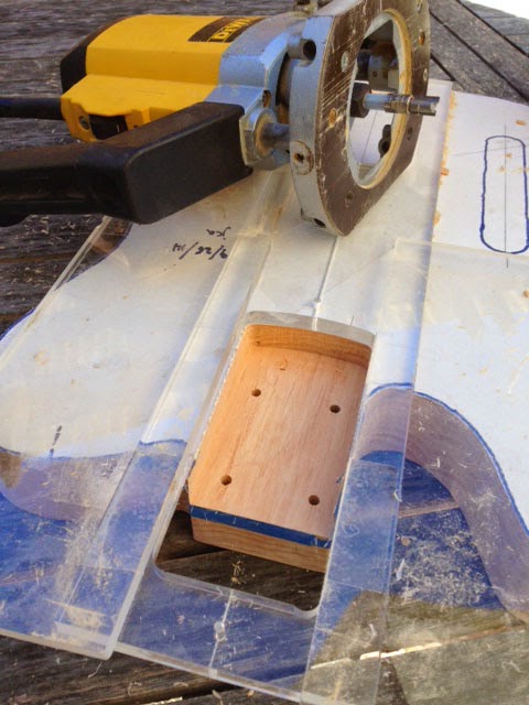

The Rondo neck is slightly narrower than the standard pocket, so I used a piece of plexiglass as a bearing guide to narrow the edges, one edge at time.  Still, I wound up with a pocket that slightly too wide.  My fault!


Checking the center line...


And shimming the neck with some business cards so that I can mark the neck for drilling the neck mounting holes.

Here's how it looked.  Tuners are Hipshot Ultralites.


The righty neck needed the nut flipped for lefty use.  I had glued it in with Superglue, but then decided that it wasn't quite centered correctly.  So I tried prying it out.

Bad idea!


Fixed it by gluing in a new nut and the wood chips.


String tree installed.  Not exactly parallel to the nut, but pretty close...


Time for some pickup placement experiments before routing their cavities.  The controls, mounted externally.


I put the pickups on plastic cubes (from Tap Plastics) and moved them around over the strings.  Double-sided tape sticks them to the body for testing.


The schematic of the controls I used for my initial testing:


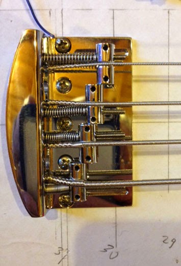
Mounted my bridge using calculation from StewMac's Fret Calculator.  That was a mistake, as it puts the bridge too close to the neck.  Note that the E string spring is almost fully compressed, while the G string is pretty far from the right edge of the bridge.  In fact, for this type of bridge (Fender 5-hole), the screw holes should be placed 1 inch longer for the scale: i.e. 31" for a 30" scale.


Drilled new holes further back and dowelled the original ones...


Ooops, the holes weren't quite straight! 


I'll get back to this later.  First, let's work out pickup placement for a 30" scale using numbers for a 34" scale (34" numbers from a spreadsheet I found on the web by B. Gavin).

(click on image to enlarge)

Playing around with two G&L pickups...


Let's try replacing one of the G&L pickups with an SCPB-3...


Final placement, after much experimenting.  Note -- to my ears, moving a pickup a quarter-inch one way or another doesn't appreciably change the timbre of the sound. 


OK, placement has been decided.  So let's do more routing.  First, drill the hole for the jack plate.


Route the control cavity, after first drilling holes at either end with a Forstner bit.


Routing the cavity for the G&L pickup.  I didn't have a correct template, but a "Bartolini BC, Nordstrand 4 String Soapbar Shape" template is pretty close.  Just needed to move it four times to get the entire cavity routed.


And routing the cavity for the SCPB-3.  First drilled holes at either end with a Forstner bit.  Then added plexiglass as router bearing guides.


Routing done!


Drilling holes between cavities for wiring.  G&L cavity to control cavity, check.  Bridge grounding to control cavity, check.  SCPB-3 to control cavity...whooops!

Plug with dowel and redrill.


Time to remove the paper template on the front.  Started sanding.  Hey, what's this gray stuff under the paper that's gumming up my sandpaper?  Guess what, it's the spray adhesive!


Tough to get off, but I found a jar of used solvent (thinner?) lying around.  Soaked a rag with it and scrubbed off the mess.

Much better!


I was curious how different tone-cap values might sound.  So I devised a way to test 5 different values, using a standard 5-position guitar pickup switch to select 1 of 5 cap values (1nF, 5nF, 10nF, 50nF, 100nF):


Here are the controls, yet to be wired.  Please note:
  1. Pickups are engaged by pushing-in the appropriate knob. Pulling-out disconnects a pickup from the circuit. If both knobs are in, both pickups connect in parallel to the output.
  2. The two sections of each DPDT push-pull switch are wired in parallel for reliability. You could use one section of each switch in lieu of both sections, if desired.
  3. The coils of the G&L Humbucker are wired in series, not parallel (I like it that way).
  4. Capacitance values are 1nF, 5nF, 10nF, 50nF, and 100nF, but in a 1nF-10nF-5nF-100nF-50nF pattern as the switch is moved from one end to the other. (That's the only way I was able to figure out how do it with this type of switch.)

Here's how the jack would look if I did it this way -- tone cap selector switch is nearest to the jack.


Wired up!


And assembled.  Not bad looking!  (Still needs paint, though.)


After playing on it a bit, I decided it needed a forearm contour.  Roughed out with rasp, then finished with an 8-inch rectangular steel pipe with 320 grit sandpaper taped to it.


With the contour finished...


And after playing around with the cap values, I decided to decrease the number from 5 caps to 2:  10nF and 47nF.  One of the push-pull switches will select the cap value.  And I changed the 5-position selector switch to a standard 3-position pickup selector, as shown in the schematic below:


Also, I noticed a bit of fret buzzing.  Guess I need to level the frets!  To do this, I first adjusted the trust rod to ensure that the neck was exactly flat (using a neck straight-edge notched for a 30" scale neck).


Then I marked the tops of all the frets with a black Sharpie and carefully sanding them (320 grit on an 8" beam) until all of the black has been touched by the sandpaper.


Next...because I'm using a righty neck as a lefty, the neck side dots are on the wrong side of the neck.  So I needed to add side dots on the other side.  I picked up some black plastic 2.0mm diameter rods on eBay.  To install the dots, I drilled shallow 5/64" holes at the appropriate locations.


I then put a drop of wood glue in each hole, stuck in the end of one of the plastic rods, then clipped it off a bit above the neck with a pair of diagonal cutters.  The cutters leave a bit of a mark on the rod (it looks white where compressed), so I then filed off the cutting marks, leveling the plastic with the neck wood using a small needle file.


I'd been planning to use Danish Oil to finish the body. Didn't know what tint to choose, so I picked up 3 different cans: Natural, Golden Oak, and Cherry. Tested them on scraps from the body, and frankly, they didn't do anything for me.

So on to Plan B: Why not seal the wood with a 2-part urethane clear coat? This is how I would normally treat the body (i.e. seal the wood) before painting a color base coat. Let's see how it looks.

So I picked up some cans of SprayMax 2K Glamour High Gloss Clear Coat. (This is a paint where you press a knob on the bottom of the can which releases the catalyst (or activator?) into the can and you have 48 hours to paint with it before it is kaput).


Note -- this is not healthy stuff. So I use a good respirator mask and goggles (and nitrile gloves...)


The temporary paint booth. Cheap paper drop cloth thumb-tacked to the wood above, with duct tape reinforcing the paper where the thumbtacks poke through it.


Not too bad!


After looking at it, though, I decided to go ahead and paint the body with the yellow paint that I'd had mixed at the auto paint store. (All painting, by the way, is done with rattle-can paints.)

First step was to sand the body smooth with 320 grit, dry, sandpaper, then spray with automotive white primer.


After priming it, I waited a day and then lightly sanded the primer with 600 grit sandpaper, dry. I then applied the base (color) coat. The base coat is automobile urethane paint, designed to be used in a dual-stage process in which the second stage is the application of a clear-coat over it. The clear-coat will be applied another day. First the base coat...

Here's how the base coat looked:


I let this sit for 24 hours, then did a very light sanding of any obvious "bumps" or imperfections in this color coat using 600 grit, dry, but for the most part I left the body unsanded. Here's my reasoning for no sanding: the clearcoat that I will apply actually melts into the base coat (or so it seems to me), and so I couldn't see any benefit to additional sanding, whereas there's an obvious downside to sanding, which is the potential thinning of the color coat so that primer shows through. I've had sand-through issues in the past, and this was a huge concern to me.

(With that said, if anyone believes it's better to sand the color coat when using automotive urethane paint, please let me know! This is the third body I've painted this way without sanding the color coat and it seems to work fine, but I'm no expert. Would love to learn more.)

After 24 hours had passed, I sprayed the first can of clear-coat. This is an automotive urethane clear-coat that, when mixed (by pressing a red knob on the bottom of the can), has a pot life of 48 hours.

I let this clear-coat cure for 24 hours, then lightly sanded the body with 600 grit, dry, and followed that with my second can of clear-coat. Here's the body after both cans have been applied:


And here are the spray cans I used for this latest stage of the build. All were purchased at an automotive paint store (in my case, "Jerry's Paint and Supplies," in Sacramento, CA):


Note that during all painting I wore a good respirator, goggles, gloves (nitrile), long-sleeve shirt and long pants, as some (or all?) of this paint can be pretty bad stuff.

I waited a week to ensure that the clearcoat was adequately cured, then on to sanding and polishing.

Sanding was done with the following progressive grits of sandpaper, wet: 600, 800, 1000, 1500, and 2000 (sharp corners were only done with 1000 and above).

Followed with Micromesh pads of coarseness: 2400, 3200, 3600, 4000, and 6000 (also wet).

And then lots of rubbing with Meguiar's "Diamond Cut Compound 2.0".

Not sure if this is the best way to do it, but it seemed to work. Still some very tiny scratches, though, visible on the body if I look closely. Advice on better methods is always welcome!

A couple of other faux pas on my part...

First, I'd used washers on the screws that held the body to the neck stick. One washer was a bit too large (both in size and inner diameter), and so it didn't lay centered under the screw. As a result, there's a fairly large patch of unpainted wood jutting towards the top of the body. Fortunately, the back plate just covers this. But lesson learned. Will need to figure out a better way of holding body to stick. Might just be a correctly sized washer (or...?).

With all of the wet sanding, it's important to keep the water away from the wood, otherwise the wood will absorb it and swell. In the first two bodies I'd painted (kit-bass bodies), I had this problem, and I thought I'd solved it this time by plugging the few holes I had with wax. And this worked well. But I'd removed the tape I'd used to mask off the neck pocket, revealing bare wood next to the edge of the paint, and a small amount of water was absorbed there, swelling the wood in a few places under the paint.

I was able to bring the swelling back down by heating the area with a desk lamp and then applying pressure with clamps (via a piece of wood). But there's still a bit of irregularity in the smoothness of the top near the neck pocket (most easily seen when using the body as a mirror and looking at reflections in it). A good reason to use a pickguard, as it will hide this. And next time I sand, maybe leave neck pocket masking on?

Sanding done, time to install the neck and all of the parts.

It's done!


By the way, this build is also documented on the TalkBass forum (where you can also see the commont of others on my work-in-progress).  If interested, go here:

  http://www.talkbass.com/threads/bass-build-short-scale-lefty-tele-bass.1105446/


Links to Bass posts of mine...

Sonic Blue Bass (part 1 of a 3 part series)

Mellow Yellow Bass

Short-scale Telecaster Bass

Bass Guitar Painting Jig

Repairing a G&L Butterscotch Blonde Paint Chip

G&L ASAT Bass Strap-button Extender

Thursday, August 7, 2014

Mellow Yellow Bass Kit Build


What?  Another bass kit?  Had I lost my mind?

I hadn't planned on building another bass kit, honest.  (See my experiences with my previous kit here:  http://k6jca.blogspot.com/2013/09/building-bass-guitar-kit-part-1.html).  But while searching ebay last year, I came upon this kit:


A classic body look similar to a '51 bass (which I've always been partial to).  And, most importantly, there was a lefty version, too!

And it had a humbucker?

OK, I was intrigued.  I'd never tried a lefty humbucker bass; this might be my chance.  But what was with the weird (and amazingly ugly) headstock shape?  Looked like the headstock was trying to morph into a pumpjack.

Well, I figured I could probably fix that with a saw.  So, what the heck.  I ordered one.

It's here!

The box arrived...


OK, first things first, I took inventory.  Everything was there this time.  But the control plate was made of plastic (the same material as the pickguard -- guess they didn't have a lefty version in metal).  And again, the nut was a righty version (the built-in slope is in the wrong direction).

But none of these were show stoppers.  So on to the next step:  completely assemble and check that it sounded halfway decent before investing time and money to reshape the headstock and paint the body.

First, mounting holes needed to be drilled for the following:
  • Pickguard
  • Control Plate
  • Jack plate
  • Pickups
  • Bridge
  • Strap Buttons
  • Tuner Screws
  • String Retainer
I also drilled out the 4 holes in the body for the neck screws -- they were too small, and the neck screws would have bit into the body wood as they were being screwed in, which was something I didn't want.  The screws should pass through the body unimpeded and only bite into the neck wood.  Otherwise, I would run the risk of not being able to adequately tighten the neck to the body.

As I assembled the bass, I discovered a few more issues.  Some of my own making, some not.

First, my mistakes:

1.  I initially mounted the bridge a little to close to the neck pocket, so that when I tried to setup the bass, I discovered that the saddles were getting very close to the back of the bridge.  Redrilled five holes closer to the end of the bass and filled the first five holes with bondo (next time will use dowels):

2.  Made the holes for the tuner screws slightly too small (I think).  One of the screws broke when I was screwing it in to the headstock: 
Had to dig a bit into the wood so that I could grab the broken-off end with a pair of pliers and unscrew it.

And the manufacturer's issues:

1.  Right-handed nut, not a lefty (slots sloped the wrong way).  I first tried filing the slots to give them the proper slope (towards the headstock, not the bridge), but this put the strings so low that they would rattle on the frets between the nut and the fret I was fretting when I plucked a string.  So I found another nut in my spares box and installed it.  (In hindsight, I probably could have just added a shim below the original nut after I'd filed it.)

2.  The pickup route was just a bit too small for the pickup's mounting ears!  Fixed with files/sandpaper applied to sides of the pickup cavity.

3.  Neck cross-section not symmetric.  Looks more like an airplane wing.  Can't fix it, but it doesn't seem to be a problem.  Just sloppy manufacturing and poor quality control.

 4.  One end of the third fret is a bit short:
Not going to fix that,

5.  Sharp fret ends:  file them down.

6.  Neck plate not squared to body (i.e. body holes and pocket not squared to body):  File the body holes for the neck bolts so that they're a bit wider, to give some room to square up the neck and sand the sides of the neck pocket to give me enough range of movement.

7.  E-string tuner slightly offset so that when only the E-string is installed, it wants to slide the nut sideways.  Not a big deal, but still...

On the plus side, the frets seem level this time.

Assembly is done, how does it sound?

Plug it in and turn on the amp.  Wow!  Lot's of hum!!!

Wiring looks OK -- let's see if shielding helps.

First, let's pick the low-hanging fruit and shield the control cavity and the plastic control plate with 1/2" copper tape from the junkbox:

Hmmm...still lots of hum.  Must be capacitive-coupling to the pickups.  Let's shield the heck out of them:

First, wrap each of the coils in copper tape:


Then add tape to the top of the pickup:


Note that these top pieces of copper tape are soldered to the copper tape on the sides of the coils, so that there isn't any solder on top of the pickup that might prevent the pickup cover from going all the way onto the pickup body.

 And finally, add copper tape to the back of the pickup:

This may be going a bit overboard, but I figured better to do as much shielding as I could, all at once, rather than piecemeal.

All pieces of copper are connected together with solder (spot-tacking is fine), and then attached to the pickup ground at one spot.

Reinstall the pickup and test:  no more hum!!!
[Sidebar on hum:  I believe that humbuckers get their name from preventing magnetic-field induced hum.  Unfortunately, the hum I usually experience is not from magnetic fields, but from electric field interference that's capacitively-coupling to the pickup windings, and unless the pickup has appropriate E-field shielding, magnetic-field counter-measures (e.g. bucking coil windings) will have no effect.

Fortunately, E-field shielding is pretty straight-forward.  What you want to do is provide enough shielding (i.e. conductive surface tied to ground) near the pickup so that the majority of the electric field interference is shunted (via capacitive coupling) to this surface, rather than to the coil(s) of the pickup.

For further reading, check out the capacitive-coupling section in Chapter 2 (Cabling) of the book, "Noise Reduction Techniques in Electronic Systems, Second Edition", by Henry W. Ott.  Great book!]

This amount of shielding will have some effect on the sonic properties of the pickup -- essentially, it appears as extra capacitance from the pickup to ground.

In this case, my shielding added about 0.5 nF to the output of the pickup.  Given that the tone-control's capacitor is 47nF, and that I usually play with the tone control near 0 ohms (i.e. fully, or nearly so, ON), this additional amount ( 1 % ) would seem to be insignificant.


An Aside on the Pickup's Placement

OK -- the bass sounded pretty good!  And I was wondering how the pickup was placed relative to the 12th fret.

The centers of the neck-side poles measured roughly 13 inches from the hump-top of the 12th fret.  That's very interesting, because, according to internet sources, the same poles on a Musicman SR4's pickup are about 13.125 inches from the 12th fret.

In other words, the placement of this humbucker is within 1/8 inch of an SR4's humbucker.  Maybe this accounts for its sound?

I was also quite surprised, because from the pictures, I thought that the pickup was higher up, placed in a position close to where a P-bass's pickup would be.  And then I looked more closely...

Hmmm -- although the pickup is placed next to the pickguard, the bridge is actually fairly far away from the rear end of the guitar.

And the neck has 22 frets, not 20, and the neck pocket isn't as "long" as a typical Fender pocket.  That is, the neck juts further out of the pocket.  (This also means that I cannot replace this neck with a neck drilled with the standard Fender hole pattern -- it won't sit far enough into the neck for its holes to line up with the body holes).

The overall net effect of these changes is that the neck and bridge have been shifted in position towards the neck-end of the body, which is the same as if they'd not been changed, but the pickup had been moved instead from the standard P-bass position to one closer to the bridge, similar to a Musicman pickup position.  But now the bass is roughly 1 3/4 inches longer than my P-bass.

I'm happy with the sound, let's continue on...


Working on the neck and headstock.

First, let's take care of that ugly headstock.

Not a lot of wood to work with, but what the heck.  Tackle first with a saw, then a sanding bit on my drill, then file and sandpaper.  Here's the result:

Much better!

Here's the bass in its fully assembled yet unpainted state:

I then removed the neck and its hardware, and then finished the neck with brushed-on Minwax Fast-Drying Polyurethane (clear satin) and hung to dry.  Once dry, I sanded down with 1000 grit sandpaper.


Painting the body

Now to paint, sand, and then polish the body.

Again, just like my previous project, I'm following (pretty much) the steps in the book, "How to Create a Factory Guitar Finish with Just a Couple of Spray Cans!", by John Gleneicki.

1.  Strip the body of all parts. 

2.  Sand the body and then fill any small dings and divots that I found with auto-body bondo.

3.  Spray the body with a can of Spraymax 2K Glamour High Gloss Clear Coat to act as a body sealer and filler.  Here's the body after this step:
The red spots on the body are bondo patches.  (The wood is so soft that it dents if you look at it sideways.)

4.  Sand the front and back of the body flat with a wood block and 320 grit (dry, not wet).

5.  Because the body wasn't too flat to begin with, this last step resulted in me sanding back to wood in a few spots.  So I sprayed another can of the Spraymax 2K and repeated the leveling of front and back with block-sanding using 320 grit (dry).

6.  Wait 3 days, then spray with primer.  When dry, lightly sand with 600 grit (dry).

7.  Spray the color (base) coat. 

Here's the primed body, waiting for base coat, in my homemade painting jig (jig described here: http://k6jca.blogspot.com/2014/07/bass-guitar-body-painting-jig.html

8.  Wait 2 days, spray with a can of Spraymax 2K Glamour High Gloss Clear Coat over the color coat.  Note: you don't need to sand the color coat if using urethane color coat.

9.  Wait another day, then sand with 600 grit (dry) and spray another can of Spraymax 2K Glamour High Gloss Glear Coat.

10.  Wait a week.

Before we continue on, let me add a few more pictures.

Here's a shot of the types of paint I used.  Middle can is the base color:  VW "Mellow Yellow", custom mixed at "Jerry's Paint and Supply" in Sacramento.  PPG code 902738.

The Spraymax can has a slightly different label from the cans I used last year: now there's "368-0061".  No idea what that means.  New formulation for California?

My painting worksheet.  Click on it to enlarge.

A tip!  If using a trigger-handle for your cans, tape it to the can.  I found that cans could rotate in the handle, and if I wasn't paying attention I'd end up painting the inside of the trigger-handle, rather than the body.


Sanding and polishing the finish

A week has passed.  Time to remove the neck stick and start sanding.

Body before sanding begins:

First, I'll note that all of the sanding is done with wet sandpaper.  I start by soaking the sandpaper in a bowl of water for a few minutes, then, while sanding, I'll frequently dip the paper back into the bowl to keep it moist and to clean it off.

This means that the body gets pretty wet!  It's important that this water not get into any holes, as the wood will swell and you can easily sand through your coats.  This time I plugged them with wax from a candle -- I let melted wax drip over each hole, and while it was still soft and malleable I pressed it into each hole.  I then gently scraped away the remaining wax (use fingernail or soft tool).

This worked very well -- no unintended swelling this time!

Regarding the actual sanding,  Gleneicki goes into a good amount of detail in his book, so I'll just summarize what I did:

1.  Sand top and bottom (but not the tummy and arm contours) with 320 grit, wet, using a wood block.

2.  Sand top and bottom and tummy/arm contours with 400 grit, wet.  No block (paper held in fingers).

3.  Sand the above, plus sides (but not edges), with 600 grit, wet, no block.

4.  Sand the above, plus gently-rounded edges, with 800 grit, wet, no block.

5.  Sand the above, plus sharply-rounded edges, with 1000 grit, wet, no block.

6.  Sand all of the body with 1500 grit, wet, no block.

7.  Sand all of the body with 2000 grit, wet, no block.

Ooops, a boo boo!

While sanding the sides, all of a sudden I saw white primer (probably because I actually used 400 grit on the sides and also didn't adequately spray on the second day's clear coat.  Next time, 600 grit!).

Heart stop!
(Click on image to enlarge)

Can I fix it?

Fortunately I had a bit of paint left in the can (tip:  don't spray it all out when painting the body.  Leave a little in the can, just in case).

So I masked off the body, revealing only the primer and a bit more of the body around it...
...and sprayed it with color: 2 tack coats, 3 (or was that 4?) wet coats.

After the paint had dried, I sanded down its edges and then added an enlarged mask for a new layer of clear coat (fortunately, I had purchased an extra can of Spraymax 2K.  So the cost to fix the boo-boo:  $20!).

(Clear coat:  2 tack coats, 4 wet coats).

Here's the body, waiting for the clear to cure.

After a few days I removed the mask.  If you look closely, you can see the edges of the new clear coat.
(Click on image to enlarge)

I then sanded the new clear coat patch, removing its "orange-peel" and blending its edges, first with 1000 grit, then 1500, then 2000, all wet.  Here's how it ended up:


Looks pretty good to me!


Polishing the finish:

After the final sanding with 2000 grit, I polished with Turtle Wax "Polishing Compound" that I'd picked up at a hardware store.  Rubbed and sweated, rubbed and sweated, rubbed and sweated (hey, it's summer, and it's been hot and humid recently!)

Finally got it to a point that I was satisfied with it.  The surface isn't as flat as I'd like it to be (i.e. perfectly flat), but it has a nice mirror-like sheen.

Here's the end result:


Not too bad!


Final Thoughts:

1.  The new Spraymax 2K seems to take a bit longer to cure (but I could be wrong).  I have some very small dings in the body where some hard objects pressed into the body (such as my car keys in my pants pocket) while I was holding the body against me and aggressively polishing its sides.  Not a big deal, but maybe try 2 week cure before starting sanding?

2.  In the same vein, pot life in the can seems to be longer than 24 hours.  With the can I used to fix my mistake, I noticed that it seemed good at least 48 hours afterwards (and perhaps 72?).  Again, perhaps it's a new formulation?

3.  Next time, I might try sanding with higher grits before I begin polishing.  Perhaps 2500 or 3000.

4.  Don't use bondo to fill holes -- it shrinks as it drys, and thus can sink.  Use bondo for shallow dents and dings.  Fill holes instead with wood dowels.


And the standard caveat:

This is a learning process for me.  Never assume that what I've done is the best way to do it, or even the correct way.  Use your own judgement and common sense.  Or ask an expert.

And if you know of a better way to do something, please let me know.  I'm always interested in learning new tips and techniques!

And one more thing...if you're thinking of buying a kit to save money, don't do it!  You can get a decent guitar, used, for less money than you'll spend on the kit plus paint plus tools.


Links to Bass posts of mine...

Sonic Blue Bass (part 1 of a 3 part series)

Mellow Yellow Bass

Short-scale Telecaster Bass

Bass Guitar Painting Jig

Repairing a G&L Butterscotch Blonde Paint Chip

G&L ASAT Bass Strap-button Extender

Monday, July 28, 2014

Bass Guitar Body Painting Jig

When I painted a bass guitar body last year, this was the technique I used (described here:   http://k6jca.blogspot.com/2013/09/building-bass-guitar-kit-part-2.html):

Not a great way to do it.  The bass body was awkward to hold, and the paint layers around the bottom edge were too thin because of the difficult painting angle.

So, when I recently decided to paint another bass body, I thought it best to make some sort of jig to hold the body during painting.

Here's what I came up with, using materials purchased at the local hardware store:


During the painting process (e.g. primer coat, base color coat, and clear coats), the body is mounted to an assembly that is never removed.  This assembly consists of a neck stick (short length of hardwood, attached to the neck via the body's neck holes).  And as part of this assembly this stick is attached, in turn, to an 18" length of 1/2" pipe, using a pipe flange and some couplings.  This pipe allows me to rotate the body in the jig and also lets me hang the body vertically while a paint coat cures.  More on this later.

Here I'm holding the "neck stick assembly":


Here's the basic jig with the bass body and its "neck stick assembly" removed.


To build this jig I used the following materials:

The base mounting wood is a piece of Melamine Shelving (23 3/4" x 48" x 3/4").  But any scrap wood of the appropriate size should be fine.

Two 1/2" Floor Flanges are attached to this base.

The vertical pipes are each 1/2" x 36" threaded pipes.

These each go into one end of a 1/2" Tee.

The horizontal member between the two 1/2" Tees is a 1/2" x 12" threaded pipe.

And into the top of each Tee is screwed a 1/2" x 1" length of threaded pipe.

All of these pipes are screwed down tightly!


I've screwed a 1" x 1" x 1/2" PVC reduction Tee onto the tops of each of the two 1/2" x 1" threaded pipes.

Here's a closeup of the left-hand one.  Short lengths of 1" Schedule 40 PVC pipe are glued into each end of the Tee.


And here's the other PVC Tee.  I hacksawed slits into the PVC piece glued into the left-side of the Tee,  and I placed a hose clamp over the slits.  This hose clamp, when tightened, securely holds the body at any rotational angle I desire.


Here are the two floor flanges, with the vertical pipes screwed into them.  I tightly attached the pipes to these flanges (and built the rest of the jig) before I mounted the flanges onto the bottom piece of wood.


To keep the jig from rocking on the nuts holding the flange screws to the bottom-side of the wood mount, I attached lengths of inexpensive 11/16" x 2 3/8 furring strips along the bottom sides of the wood mount.


Here's the assembly that attaches to the base body:

I've attached a 1/2" floor flange to the "neck stick"

A short length of 1/2" threaded pipe attaches the floor flange to a 1/2" Tee.

Into the Tee is threaded an 18" of 1/2" threaded pipe.

(Tighten down all these joints!)

I also screwed in a 1/2" PVC threaded coupling into the 1/2" Tee, and into this coupling I glued a scrap piece of 1/2" PVC pipe.  This the handle I use to rotate the bass body.


By the way, if the hose clamp is really tightened down hard, the 18" pipe won't move while you rotate the body.  NOT GOOD -- this means that pipe is unscrewing from the Tee attaching it to the bass' "neck stick" when you are rotating it.  Worst case:  the body will unexpectedly fall to the ground.  

Oops!

So I added a little note to remind myself not to over-tighten the hose clamp.

After the body is painted, I hang it vertically to dry.  To do this, I made a hook assembly that I can screw onto the end of the 18" piece of 1/2" pipe that is part of the "neck stick assembly".

Here's what the hook assembly looks like:


I drilled a hole in a 3/4" threaded PVC cap and then attached a hook.  A 3/4" x 1/2" PVC bushing is then threaded into the cap.

There's a nut on outside of the cap (see picture above) and a nut on the inside (and you can also see internal threads of the PVC bushing).


Here's the hook assembly screwed onto the end of the 18" pipe:


 And here's the body, hanging to dry after I had applied its sealer coat.


Here are some pictures of the jig in action, in my home-made paint booth (using inexpensive 9' x 12' paper drop "cloths" above and below):

Primed body, awaiting color:


 Color coat being applied (Volkswagen "Mellow Yellow"):


Another shot of the paint booth.  The inexpensive paper awning is thumb-tacked to a wooden arbor and the paper, where the thumb-tacks penetrate, is reinforced with short pieces of duct tape, so that the paper doesn't rip.


That's it!

Update:

There's an interesting discussion on the Talkbass forum  regarding this jig and others (there are some very clever designs).  You can read it here:

    http://www.talkbass.com/threads/jig-for-painting-a-bass-body.1092902/


Links to Bass posts of mine...

Sonic Blue Bass (part 1 of a 3 part series)

Mellow Yellow Bass

Short-scale Telecaster Bass

Bass Guitar Painting Jig

Repairing a G&L Butterscotch Blonde Paint Chip

G&L ASAT Bass Strap-button Extender