Monday, September 14, 2009

PRC-47 Modifications


[2 December 2010: Added an Addendum to the "Replacement of the Switching Supply Power Transistors" section, below.

8 February 2011: Added another Addendum at the very end of this post.]


The PRC-47 is a Vietnam War era SSB transceiver designed to operate from 2.000 to 11.999 MHz in 1 KHz steps. It is USB only, but can also operate CW or FSK, and it's designed to be powered by either a DC supply (from 24 to 28 VDC) or a 115 VAC, 400 Hz supply.

Transmit power (into a 50 ohm load) is rated at 100 watts PEP (High Power Position) or 20 watts PEP (Low Power Position).

Here are some pictures of my PRC-47:

(Click on Image to Enlarge)

Note the modular construction with plug-in modules...


...And an easily accessible chassis:


Replacement of the Switching Supply Power Transistors:

I've had several PRC-47 transceivers in which the two 2N1653 transistors (used to convert the 24 VDC to 24 V "square-wave" AC) were bad. I replace these two transistors (Q1 and Q2, on the chassis, just under the faceplate) with more modern 2N5884 transistors, which seem to work just fine.


[Addendum, 2 December 2010]

The original transistors used for Q1 and Q2 in the Switching Power Supply are Germanium, and are either 2N1166, 2N1653, or 2N2287 transistors (I have one Tech Manual that specs the 2N1653, and another which specs the 2N2287, and others have told me that the 2N1166 is also used in some units).

Germanium transistors are difficult to find, so, to replace the original "failed" transistors, I chose a more common Silicon PNP transistor. The 2N5884 which I use is not a perfect match for the original transistors, but it's close. Here's a comparison of the specs of the three original transistors (from
the fourth edition (1969) of Motorola's "The Semiconductor Data Book") versus the 2N5884 (from ON Semiconductor's website):


It's worth noting that diodes CR1 and CR2 in the Power Oscillator are there to limit the collector-emitter voltage of transistors Q1 and Q2 (the 2N1653 transistors) to 26.5 volts, so, assuming the diodes are still OK, the 2N5884's max rating of 80 volts should provide plenty of headroom. (I haven't made any measurements to verify this, though).

If anyone is concerned about breakdown voltage, you might try experimenting with the MJ15004 transistor -- it's rated to 140 VDC. However, its Ic (continuous) rating is only 20A, versus 25A of the 2N5884, so there's a tradeoff. Personally, I'd go with the 2N5884.

By the way -- the higher Vce(sat) of the 2N5884 (or MJ15004) might result in a lower plate-voltage to the PA tube (because the voltage swing at the primary of T1 will be lower (26.5 VDC - Vce(sat)), and thus lower output power. I haven't verified this, but if you find it to be the case, you can try bumping up your DC input voltage to, say, 28V, to help counteract the swing limitation due to the higher Vce(sat) of the Silicon transistor.

(And whichever transistor you use, please report back with your results!)


PTT Not Working?

If PTT doesn't work on your radio, check the following:
  1. Ensure that CR18 is installed in the AF Amplifier Module (I use a 1N4148).
  2. Ensure that the "PTT" wire (green, in my set) is connected to J2.11 on the chassis (this is the DB-25 jack into which the AF Amplifier Module plugs). If not connected, you might find it tucked to the side.
(Note: It's possible that very early versions of the PRC-47 don't have a PTT function, but are VOX only. I have an "Advance Copy" of TM 11-5820-509-35, dated November 1963, which shows no connection to pin 11, nor the existance of CR18 in the schematics (I presume the set, at that time, was VOX only). However, my later (electronic) version of the manual, dated July 1974, shows these connections.)


LSB Modification:

A radio which only operates USB in the range of 2 to 12 MHz is of limited use to a radio amateur. However, the PRC-47 can be easily converted to LSB operation. To do this, you need to replace the mechanical filter in the IF module (which happens to be a 500 KHz, LSB filter) with a 500 KHz, USB filter. And voila, you'll have LSB.

Here's how I make this modification:
  1. Remove the Amplifier-Modulator module from the radio and remove its covers.
  2. Remove the mechanical filter and replace with a Collins F500-Z4 (or equivalent) filter.
  3. Apply +20V to P4 pin 3 (this will supply power to the module) and the 20V return to the module case. (I find it easiest to attach +20V to the far left side of L9.)
  4. Set a signal generator to 501.5 KHz and apply the signal to J3.
  5. Measuring at J1 (with either a scope or spectrum analyzer), adjust the generator's level so that you see a signal (but don't overdrive the module), then...
  6. peak the measured signal by adjusting the two variable caps, C15 and C17.

AGC Modifications:

In my opinion, the "stock" PRC-47 AGC design results in severe and unnecessary distortion of the receive audio signal. One of my first goals was to attempt to improve the quality of the receive audio. In trying to fix the AGC I'd find a solution to one problem, only to then have another problem (previously hidden) reveal itself to me. And so the modifications, like coral, grew by accretion. Thus, they may not all be necessary (because a later mod may actually cancel the need for an earlier mod), but it would take much more time to determine which mod is irrelevent and which is not, so I've left them as I've implemented them.

First, a bit of background...the PRC-47 AGC is audio derived and results in two AGC signals: -AGC (which controls the gains of the the input RF preamp tubes) and +AGC, which controls the gain of the IF stage.

For SSB operation the PRC-47 has, in my opinion, an AGC decay time which is much too fast. The +AGC line is the dominant actor for normal SSB signals, and thus, to increase the decay time of C42, I changed R74 from 22K to 220K, and then added an emitter-follower (2N2222) to keep C42 from being loaded by successive stages.

I found, though, that when I did this, signals at normal "everyday" signal strengths sounded good, but very strong signals still distorted. A bit more investigation revealed that, with very strong signals, the +AGC signal was being driven so high that it was driving the IF stage transistors (Q2 and Q3 in the Amplifier-Modulator module) into cutoff!

I fixed this by limiting the the level to which the +AGC signal can go with a 13V zener (which, in my radio, results in a clamp voltage around 12.6 volts). Not elegant, but it keeps the IF transistors out of cutoff, and the -AGC signal (which kicks in at higher levels, and which is not limited) performs the AGC function for those very loud signals. (By the way, the 390 ohm resistor that I added between the emitter of the Emitter-Follower and the +AGC line limits current when the zener is driven into conduction, and the 22K provides the original resistance-to-ground as seen by the Amplifier-Modulator module and provides a necessary bias path for the transistors in the Amplifier-Modulator module.)

(I actually use the signal at the emitter of the emitter-follower to serve an "S-Meter" function (described later) because, at the emitter, the AGC voltage isn't clamped by the zener. Thus the S-Meter covers a wider voltage range than it would have otherwise if I'd used the +AGC signal. This signal (from the emitter-follower's emitter) I call "Buffered AGC+", and I connected it to a spare pin on the module's DB-25 plug (pin 12) so that I could then route it over to the meter circuitry located elsewhere in the chassis.)

Another problem I encountered: after releasing PTT, there was increased noise from the speaker (lasting for about a second) until the AGC stabilized the signal level. When I monitored the voltage across C42, I'd see its voltage actually drop momentarily (thus increasing receiver gain) when I transitioned from Xmit to Receive, and then it would recover. Removing C35 eliminated this noise burst.

After I had removed C35, I discovered that sometimes I'd lose output power during xmit. When this occurred, I noticed that the +AGC voltage was rising (and thus cutting off IF amplifier gain). I suspected that noise on the +26VDC line might have been affecting AGC during transmit (because C35 was removed), and I modified the circuit to use the +20 VDC line instead. Note that this required paralleling R59 with a 33K resistor to keep the junction of R59/R55 at around 8 - 9 V during transmit.

Essentially, during transmit relay K1 applies 26 VDC to the VOX line. This turns on a 2N3904, which in turn switches on a 2N3905 which connects +20 VDC to R59 (less, of course, a Vce(sat) voltage drop), rather than the original 26 VDC.

Another issue: during transmit, because of the newly-added 2N2222 emitter follower, the voltage across C42 can drop to near 0 volts. Then, when switching back to receive, it's possible to have a "pop" on the attack of loud signals because this low voltage causes the gain to be too high.

I fixed this by clamping the voltage across C42 during transmit: a 2N3904 transistor turns on (during transmit), which forces the voltage across C42 to be about 3.8V (the 3.8V comes from a 3.9V zener). Then, when we transition back to receive, there's less of a difference between initial receive gain and the required receive gain. (We could actually have used a zener with a bit higher voltage (nearer, say, 4.8 to 5.4 volts), but 3.9 volts seems to work fine.)

Here are some voltage measurements on my PRC-47 with these mods:
  • Receive, no antenna connected: V(C42) = 0.4Vdc V(Buffered AGC+) = 5.4Vdc
  • Receive, 80 meters, w/antenna and atmospheric noise: V(C42) = 9.4 Vdc V(Buffered AGC+) = 8.9Vdc
  • Transmit: V(C42) = 3.8 Vdc V(Buffered AGC+) = 5.4Vdc
Here's a schematic showing these AGC Mods.

(Click on Image to Enlarge Schematic)

Here's how the implementation looks:


Adding an S-Meter:

Normally, the PRC-47's meter doesn't move when the radio is in Receive mode. I thought it might be nice to have some sort of indication of relative signal strength (having a "dead" meter always seems a bit unnatural to me). If you don't mind a meter that's uncalibrated and non-linear, then here's a simple mod you can make.

It does require using a spare pin on the AF Amplifier module to run a "Buffered AGC+" signal to the outside world (and a wire added from the DB-25 jack (J2 on the chassis) to the new components mounted elsewhere on the chassis (see photo below for component location and mounting -- I used pin 12 of the DB-25 (J2) for this new signal). You can find a description of this "Buffered AGC+" signal above, in my AGC mods. (A "buffered" agc signal is used to drive the meter in order to keep the meter from loading the AGC cap: additional loading would worsen agc performance by shortening the agc decay time.)

I simply "diode-OR'd" this new AGC voltage with the existing "Xmit Signal Strength" signal. "Diode-ORing" simply means that whichever of these two signals has the highest voltage level will be the signal which controls the meter reading.

During Receive, the "Buffered AGC+" signal runs from about 5.4V (no antenna attached) to around 17.7 volts max (for strong signals). And during xmit this signal is at 5.4 volts. The 7.5 volt zener keeps the meter at 0 when there's no antenna attached (because 7.5 volts is greater than 5.4 volts, the zener doesn't conduct), and there's a couple of extra volts of head-room to keep the needle at a reasonable (left-side of meter) deflection when receiving normal atmospheric noise. And because this zener doesn't conduct during TX either, only the Xmit Signal Strength signal feeds the meter during TX.

Xmit Signal Strength is actually a fairly low level signal (if I recall, from my measurements it's about 250 mV max), and thus I used a Germanium diode (1N34) for this side of the diode-OR because of this diode's low turn-on voltage.

The 200K resistor limits the current to the 50 uA meter so that, at the strongest receive signal levels, the meter is just at its maximum deflection.

Here's the schematic:

(Click on Image to Enlarge Schematic)


And here's its implementation. I added a terminal strip for the additional components.


Transmit Audio issues:

The PRC-47 transmit audio leaves a LOT to be desired. It has an audio "compressor" which will distort the signal. Carbon mics can sound crummy. An inordinate amount of crud from the switching supply is coupled into the signal, manifesting itself as an underlying "whine" sound.

The conversion of the 24 - 28 Volt DC source to AC (actually, a square wave), which is required to generate the other voltages that the radio requires, unfortunately results in nasty switching artifacts that appear everywhere throughout the radio (on the +20VDC line (and other signals)). The ultimate result? Whine on the TX audio.

I've worked for many frustrating hours trying to minimize this whine. I've had some success, but I've never been satisfied. Because I use an "amplified"D-104 as my mic, I finally resorted to a simple solution: apply even more gain to the D-104 signal, EXTERNALLY (so that it's much louder than the internally-coupled noise), and bypass the radio's internal gain stages (into which the noise was being injected and amplified). This doesn't completely eliminate the noise, but the noise does seem to be much less and just about tolerable.

During my attempts to reduce this whine, I tried any number of fixes. Some seemed to improve things, such as the addition of 0.01 uF from the "CW Key" signal to ground (I mounted this on the back side of the middle board in the AF Amplifier module). But many of the mods I tried had little effect.

(One likely area of coupling might be the "Mike Input" wire. This wire runs from the Mic Connectors on the front panel to J2 pin 25 on the chassis (the AF Amplifier module's connector), and during its run from the front panel to J2.25 it's bundled together with quite a few noisy wires in a wiring harness. Thus, noise coupling onto this wire is certainly a very real possibility. One mod I'd like to try to reduce this possible coupling is to replace the wire with a shielded wire (e.g. coax). Unfortunately, on my radio, the Mic Connector pins to which this wire connects are difficult to get to. So, I'm leaving this for another day...)

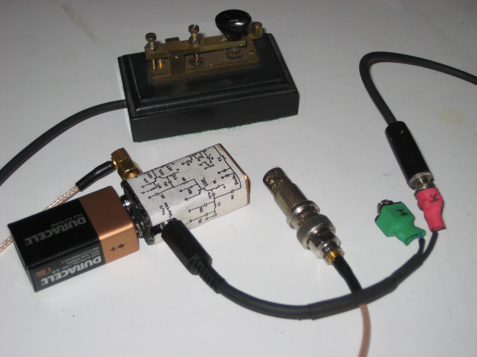
Here's the External Mic Preamp which I built to drive the PRC-47 (I needed more gain, even though I'm using an "amplified" version of the D-104 mic):


And here are the mods I made to the mic amplifier side of the AF Amplifier module:

(Click on Image to Enlarge Schematic)

(I recognize that this solution really only suits my particular situation, and it is of little use if one wants to use a carbon handset or mic with the radio. So I encourage readers to experiment and discover what works for them. One tip I can give -- a friend, Dick (W1QG), replaced R2 (47 ohms) with a current source (about 600 uA), and also added emitter degeneration to Q1 and Q3, to lower the gain of both of these stages. This apparently helped out when using a carbon mic.)


A note on how I adjust the "MIC AMPL GAIN" pot (R27) on the AF Amplifier module...

Adjustment of this pot is described in section 3-26 of the Tech Manual (TM 11-5820-509-35). I'm lazy, so rather than attach a generator to the mic input, I adjust R27 using the TUNE signal (when in Tune Mode) so that it measures 3.5 vpp at the measurement point (see section 3-26.b). Then, once I have R27 set to 3.5vpp for the TUNE signal, I adjust the gain of my EXTERNAL mic preamp to also give 3.5 vpp at the same measuring point (for voice peaks). (Note, diodes CR5 and CR6 act as limiters, and they limit both the TUNE and the mic's audio signals -- if you're using an external mic preamp and you set its gain too high, you'll grossly clip your audio signal, which can add distortion. The TUNE signal, by the way, isn't a nice sine-wave, but is clipped by CR5 and CR6.)

If the radio is already buttoned up, I adjust the gain of the External Mic Preamp to give the same envelope peak voltage on the RF output (monitored with a 'scope) that I get in the TUNE position.


Curing that "Donald Duck" sound on Sidetone:

During Transmit the PRC-47 can insert a small amount of the TX audio back into the receive path so that operators, while transmitting, can hear themselves talking. This audio is called "sidetone", and its usage comes from the telephone world, where it was found (allegedly), that if people heard themselves in their telephone handset's earpiece while they talked, there was less of a tendency for them to yell into the mouthpiece.

Unfortunately, the PRC-47's sidetone signal can sound very distorted (I liken it to "Donald Duck"). The cause seems to be an audio envelope that appears on the "Sidetone Gate" signal during transmit. I improved this by adding a 4.7 uF cap from the "Sidetone Gate" line to ground in the AF Amplifier module (cap '+' goes to ground, cap '-' goes to Sidetone Gate).

If using an external speaker in lieu of a handset (which I do), sidetone can be quite annoying, so I also turn the sidetone gain potentiometer (R46 on the AF Amplifier module) all the way down.


Other Notes:

1. Extender Cables.

When working on the PRC-47, it's nice to have a set of extender cables that will let you remove modules from the chassis for debugging/experimentation, yet allow them to remain attached. Cables for this purpose actually exist, but are difficult to find. However, it's easy enough to make one for the AF Amplifier module (which uses a DB-25 connector). Here's the one I made (shown in use):


2. Documentation:

Get the latest version of the Tech Manual (TM 11-5820-509-35). The one I have is in electronic format (PDF), dated July 1974. Various modules have been modified over the years (from the initial design), and it's worthwhile having the schematics for the latest designs (Chapter 1 lists the various changes that have been made to the radio since is inception).

However, there is one caveat regarding this manual: there ARE errors! The text was (apparently) read in via OCR, and the usual goofy OCR mistakes are the result (I guess proof-reading was either sloppy or non-existant). Also, the schematics can have errors. I've run across a few, but, fortunately, not many.

(Also -- I always keep a lab notebook nearby in which I jot down notes, modifications, and measurements as I'm going along. It's a habit I got into as an engineer and it helps tremendously when, years later, you're looking over a schematic and wondering, "Why the hell did I do that?" Which is exactly what happened to me when I started writing up this post on the PRC-47 -- many of these mods were made six years ago, and it was no longer clear to me why I'd made some of them. Fortunately, a quick glance through my lab notebook quickly resolved any questions that I had.)


3. Pot Settings.

I usually set the following pots as follows:

On the AF Module:
  • R46 (Sidetone Gain): Full CCW
  • R52 (AGC Gain): Full CW
  • R54 (Rcvr Gain): Set per manual (section 3-22). Or use your ear.
  • R27 (Mic Ampl Gain): See Note above (in the "Transmit Audio Issues" section).

4. Setting TX Gain:
  • See sections 3-27 and 5-4 in the Tech Manual.

5. Power Amplifier Bias Adjustments:

Per Dick, W1QG, the PA bias should be set so that the PRC-47 "idle" current (from the 24 volt DC supply) during transmit is 6 amps ("idle" means that there is no TX audio). Using the instructions in section 3-27.c of the Tech Manual, adjusting the bias so that the voltage at A5J2 is -140 volts, instead of -110 volts, seems to achieve this goal.

6. Replacing bad transistors in modules...

Many (if not all) of the transistors used in the PRC-47 are germanium, not silicon, devices, and, if they go bad, identical replacements can be difficult to find. Whenever I come across a bad transistor, I've had good success simply replacing it with a silicon device. For example, I might replace a bad PNP with a 2N3905, and a bad NPN with a 2N3904 or 2N2222 (because I have lots of these devices lying around my "lab"). Silicon devices have a higher Vbe, but not significantly higher considering that much of the PRC-47's circuitry is biased from 20 volts. Thus, I don't believe that use of silicon devices will significantly alter the bias point (and therefore, potentially, the gain) in much of the PRC-47 circuitry.

Also -- pay attention to the transistor's application. You want to ensure that whatever replacement transistor you choose won't get smoked! Fortunately, you can still locate specs for many of the original 'Ge' transistors on the web, and a quick comparison with a replacement 'Si' transistor's specs should tell you if your choice is adequate.


A Final Note!

It's always possible that I've made a mistake in these notes (or during the implementation of these mods). If there's something that looks wrong or suspicious to you, please feel free to contact me and let me know.

Many thanks!!!

- Jeff, K6JCA


Addendum, 8 February 2011 --

I've just received a note from Ron Boltz, K3TZJ, who writes:

Finished my PRC-47 sets that were here with two more arriving this week. I sent you some other info a month or so ago. Two sets had 2N2638 transistors in them so another number to add to the list.

I got to do some testing on the last set with 2N5884s installed. The frequency of the inverter goes up to 525Hz and the high voltage goes up to 1,710. The bias also increases to -132 volts. I discovered that the bias needs to be adjusted on some sets as the PA tube overloads if not set correctly. Several sets had the bias way low for some reason.

Three of the sets I worked on had the key lines cut at two places. Drove me nuts till I discovered them. One cut prevented the 800Hz oscillator from running during the tune cycle and the other place was on the PA over temp switch which prevented keying. All three sets were Marine Corp sets and had the same depot stickers on them. I wonder if this was a method of de-mil?

Ron Boltz

K3TZJ

http://www.rattrig.com


Friday, August 21, 2009

James Bond's 9V QRP Transceiver

OK, perhaps it's not quite as elegant as a "Q" creation, but hey, I can see Sean Connery pulling this little gizmo out of his pocket for some quick QRP action whenever there's a lull between seducing women and saving the world.

I built this back in '96 (when I was still WA6AHL). I was inspired by a couple of ideas -- the first was a description of the "Pixie 2" transceiver which appeared in the December, 1993 issue "QRPp" (the Journal of the Northern California QRP Club). The Pixie 2 had been built into a 35 mm film canister, which I thought was a pretty cool idea. Then there was some chatter on the QRPp list about a new design by Wayne Burdick, the "Forty-Niner" (a forty-meter, 9 volt transceiver). He hadn't yet published the schematic, but there was a parts list available, and I started thinking...a 9 volt battery shell would be the ideal housing for a 9V transceiver -- the battery connector is built-in!

So, inspired by the idea of Wayne's "Forty-Niner" and using his parts list as a starting point, I undertook my own design, which, through the judicious use of whatever surface-mount components I could find, allowed me to cram everything within the 9V battery case.

An SMA connector serves as the antenna jack, and I bring both key and headphones into the radio via a single 1/8" stereo phone jack (Tip = headphones, Ring = key). An adapter cable breaks out these two signals into two seperate jacks.

(Click on any image to enlarge.)

"Input Attenuation" and "VXO frequency control" are handled via two pots on the opposite side of the battery from the battery connector. Screwdriver controlled!


The complete setup, minus only an actual antenna and the headphones (which plug into the "green" connector).


Here's the schematic. Click on the image to enlarge...


(Note, in hindsight, I didn't need to add C15 (which I installed as a DC block) -- the xtal will also block DC.)

I've had it on the air a few times -- with a 9V battery the power out is about 300 milliwatts (900 mW with a 12V battery), and I've made contacts in California and Oregon. It's a bit too small to operate the controls comfortable (given that they're screwdriver adjustment), never the less, it was a fun little project to design and build. An article describing this design in greater detail appeared in the September, 1996 issue of QRPp. It's titled, "The Everyready: a 9V Direct Conversion Tranceiver."

Wednesday, August 19, 2009

Other SB-220 Repairs and Modifications...

Replacing the Zener, ZD1:

As I mentioned in my previous post, my SB-220 also had a blown zener diode (ZD1) and two smoked resistors: the 1 ohm power resistor (R1), and the 0.82 ohm power resistor (R3).

(BBQ, anyone?)

Luckily, I have a well-stocked junk box and I quickly found a substitute 1 ohm power resistor. To create the 0.82 ohm power resistor I paralleled two "junk box" 1.6 ohm power resistors. (the resultant 0.8 ohms is within 2.5% of the original 0.82 ohms -- close enough!)

The zener was a different problem. The SB-220's part's list called out a 1N3996A zener (5.1V, 10W). Well, the closest I had in the junk box was a 1N3995A (4.7V). But I thought I could do better than this.

A number of other posts on the Internet mention using series-connected rectifier diodes to achieve the appropriate voltage drop. Typically, they'd show 7 or 8 diodes in series, which, if forward biased, will put the voltage somewhere in the 4.9 - 5.6 volt range, depending upon the number of diodes and their characteristics (forward voltage drop is usually in the range of 0.7 to 0.8 v per diode).

An advantage to using diodes, too, is that it allows the bias voltage to be "tweaked" in steps of around 0.7 volts, thus allowing one to get close to the preferred no-signal plate current. (Per Heathkit (ref. Bulletin SB-220-1 @ SB-220 Service Bulletins), no-signal plate current (in CW/Tune mode) should be between 90 and 120 mA, and per Rich Measures' web site, the no-signal plate current in SSB mode should be between 160 and 200 mA for best linearity (lowest distortion)).

So I created a series-string of 8 diodes and connected them in place of ZD1. I used 1N4001 diodes, which are rated at 1 A. If one wants to be extra safe, use 3A diodes (such as those in the 1N5400 series), but I went with the 1 amp variety because I had a junk box full of them (and I believe that the SB-220 Rectifier Board replacement available from Harbach uses 1A diodes as their zener replacement, too).

(Click on image to enlarge)

Diode reverse-voltage rating is not that important because the diodes are not reverse-biased. And the 0.01 uF cap is just to keep RF out of the diode string.

I installed a board with 8 diodes and started testing the no-signal plate current. With 8 diodes, the Plate Current meter reads 80 mA no-signal plate current in CW/Tune mode, which is just a bit below the minimum that Heathkit recommends (90 mA). However, 6 diodes gives a plate current of 100 mA, and the no-signal current in SSB mode is 160 mA -- right at the lower end of what Rich Measures recommends. So I shorted-out two of the eight diodes to give me the final count of six.

(Click on image to enlarge.)
The 2 right-hand diodes have been shorted-out, leaving 6 diodes in series.
And just behind the board you can see the two resistors paralleled to make 0.8 ohms.

Replacing the Plate-Voltage Voltage Divider:

Another problem I discovered was that the three 4.7 Mohm, 2 Watt resistors (R6, R7, and R8) used to divide down the Plate Voltage (for the Plate Voltage meter) were all bad (one was open, one read 20 Mohms, and the third read 6 Mohms on my DVM). Per other reports on the web, failures such as this were due to the resistors being greatly overstressed (they're each subject to somewhere in the range of 750 to 1000 volts, and (allegedly) the original resistors were only rated at 350 working-volts dc). Unfortunately, didn't have any resistors with a high enough working voltage spec in my junkbox.

Instead, I decided to replace them with series-strings of lower-wattage resistors, which would allow me to divide the overall plate voltage (for this purpose assume 3 KV) amongst a greater number of resistors, so that each resistor sees a lower working-voltage.

I replaced each 4.7 M, 2 watt resistor with a string of four 1/4 watt resistors. For two of the three original resistors I used four 1.2M, 1/4 watt resistors for each 4.7 M resistor. For the third 4.7 M resistor I used three 1.2M, 1/4 watt and one 1M, 1/4 watt resistor. Total resistance is 14.2 Mohms, which is close enough to the original 14.1 Mohms.

(Click on image to enlarge)

The working-voltage rating of 1/4 watt carbon-film resistors can be either 250 VDC or 300 VDC. I don't know the manufacturer of my resistors, so I'm going to assume my resistors are 250 VDC. If we assume a 3KV max plate voltage, will we be within the working-voltage specification of these resistors?

Doing the math, given 3 KV across the entire string, then each of the eleven 1.2M ohm resistors should have just a bit less than 250 VDC across it. The single 1M ohm resistor should have about 200 volts across it. So the working-voltage for the 1.2M resistors is right at the maximum, but, given that my PA voltage actually runs less than 3KV (even in SSB mode), we actually have a bit more margin.

Also -- in this application each resistor only dissipates about 62 mW, so it's OK to use 1/4 watt resistors. It's really their working-voltage rating that we care about.

(By the way, when installing the resistor strings, don't forget to keep them away from each other and away from other components or chassis parts that they might short to).

Protecting the Meters:

Here's a simple mod that should prevent another blown out meter (such as happened to me with my Plate-Voltage meter). I used two 1N4001 diodes per meter. The mod is this: at each meter connect the anode of one diode and the cathode of the other diode to one of the meter's terminals, then connecd the opposite leads of these two diodes to the meter's other terminal (the end result: two diodes in parallel across the meter's terminals, one diode is reversed from the other diode). Do this for each meter.

(A note: the meters will hit full-scale if the voltage across them is 280 mV or greater. Silicon diodes such as the 1N4001 can actually develop a forward voltage of more than 1 volt for currents in excess of 1A. This means that you could possibly have 700 uA (or a bit more) running through your meter's coil, instead of the 200 uA. I don't see this as being a problem (I think it unlikely that the coil will burn out with 3.5x the full-scale current).

Adding a Keying circuit for Solid State Transceivers:

The amplifier keying jack has 120 volts across it, which can be deadly for solid-state transceivers. Here's a circuit I made (defined primarily by parts I had in my junk box). It's based upon a design by K8SS in the January, 1988 issue of QST but, because I didn't want to use the high-power, heat-dissipating resistor used in that original design, I instead modified it to be low-current (it uses a few extra parts -- but hey, they were already in my junk box).

(Click on Image to enlarge)

The relay in my SB-220 has a coil resistance of 4.6K ohms, which means that, when keyed on, about 30 mA will pass through it. An MPSA42 transistor has a minimum beta of 40 (at Ic = 30 mA), so to give myself a bit of base-drive margin (because I wanted to keep my currents low to minimize power dissipation) I simply hooked two together in a Darlington configuration. The 10K ohm resistors at the bases of these two MPSA42 transistors are simply there to dump any charge in their base regions when drive to them is removed.

The zener diode/MPSA42 circuit acts as a simple voltage regulator, and it provides just about 12 volts with minimal heat dissipation (because of the low-current operation). The 0.01 uF cap is just an RF bypass at the high-impedance node.

The 1N4148 adds some extra input protection, and the 1N4003 is actually across the relay coil, and snubs the voltage spike that occurs when the relay turns off.

Here's my implementation -- the parts are a bit jammed together simply because, when I started building it, I wasn't sure which of two pre-existing holes in the board I wanted to use for mounting it.


Other Notes:

1. Whenever removing the SB-220 from its cabinet, or when removing the top of the internal cage, be sure that the SB-220 is unplugged from the AC mains. Also, if the unit has been powered-up, first wait a LONG time (to allow the High-Voltage (HV) to decay down to safe levels) before removing the cover, otherwise you stand a good chance of blowing a component (such as the 0.82 ohms resistor) when the interlock shorts out the HV (been there, done that!).

2. The Internet has a wealth of information on modifying SB-220 Linear Amplifiers. Take a look around!

Caveat:

IMPORTANT NOTE: Use care whenever modifying equipment. Do not undertake these modifications if you are unsure as to how to implement them, or if you do not understand why these mods were implemented in the manner shown herein. Any time you modify your equipment, you do so at your own risk.

SB-220 Meter Repair

I'd decided to work on a Heathkit SB-220 Linear Amplifier with a bad Plate Voltage meter (as well as a couple of smoked resistors and a bad zener diode).

The simplest way to fix the meter would be to find a replacement. Unfortunately, I couldn't find any on the web (although I suspect they show up on ebay now and then). However, I'd read posts on the Internet about how others had substituted a meter movement from a Heathkit SWR meter for a blown SB-220 meter. I had a couple of old HM-2102 meters that I'd picked up at various swapmeets, and I thought I'd give it a try.

First thing to do, though, was to characterize both the meter that I was replacing and the meter from the HM-2102. Because the SB-220 Plate Voltage meter was shot, I characterized the SB-220 plate current meter (assuming both meters used identical movements), and I discovered that the meter was 1400 ohms and that it was 200 uA Full Scale. I measured the meters in the two HM-2102 SWR meters, and they each measured 1000 ohms and 100 uA Full Scale.

So, to make the HM-2102 meter's characteristics equivalent to the the original SB-220 meter, I would need to modify it so that it had 1400 ohms resistance and 200 uA full scale.

1400 ohms and 200 uA means that, for a voltage of 0.28 volts across the meter, the meter should read full scale. To make the 100 uA meter read full-scale with 0.28 volts across it, I would need to insert an 1800 ohm resistor in series with the meter. Then, to make its overall resistance 1400 ohms, I would need to connect a 2800 ohm resistor in parallel across the meter/1800 ohm resistor combo.

(Click on image to enlarge)

So, I took apart one of the HM-2102 meters so that I could start modifying it, only to discover that it had a huge magnet, and this magnet blocked the SB-220's meter-illumination light bulb from being inserted into the back of the meter.

I wondered if the second HM-2102 meter would have the same problem (per other internet postings, it seemed that Heathkit often used different meter movements for the same product). I took apart this second HM-2102 meter and discovered that it used a different magnet structure, and that this magnet provided room for the light bulb. So that was the meter to use!

Here's a photo showing the different meter movements (from their backs). The meter on the left is the first HM-2102 meter with the too-large magnet (it also has a series 1800 ohm resistor that I'd installed before I discovered the problem with the lamp installation). The second meter is the HM-2102 meter that I used, and the third meter (at the right) is the original SB-220 meter. (Click on photo to enlarge.)


Here's the final modified meter. You can see the 1800 ohm resistor in series with the meter, and a 2740 ohm resistor (close enough to 2800 ohms) in parallel across the meter terminals. (Click on photo to enlarge.)


Neither of the HM-2102 meters had their mounting holes for the faceplate in the same position as the SB-220 meter (and each was different from the other), and so I had to add two new holes to the original SB-220 faceplate (these are the two lower holes). (Later, when I mounted the faceplate, I discovered that I had to cut away some material from the faceplate because of interference with two other screws on the meter movement, but this isn't shown in the photo below.)


The HM-2102 meter movement also has a pivot-point that is lower in the meter than the pivot point in the original SB-220 meters. This means that the needle isn't a true "radius" of the meter scale, but instead has some angular offset at either extreme of its travel, as can be seen here, in this photo of the finished, modified meter (the needle crosses the meter mark at an angle, rather than being coincident with the meter marking).


All in all, it isn't an ideal solution, but at least the meter now works!

Monday, March 23, 2009

Rikstelefonen Type E.B. 21 Telephone

Some time ago, one of my relatives brought this wall-mount telephone back from Norway (it had been in the Oslo apartment of my step-mother's parents from the mid 40's until 1980), and he asked me to take a look at it to see if it could be made to work on the American phone network. (He'd be happy just to hang it on his wall, even in a non-working state, but a working phone would be so much cooler!)


The only identifying labels on the telephone are "Rikstelefonen" on the front (just below the dial), and a sticker on the back panel that states, "Type E.B. 21". Given that the phone came from Norway, I'm assuming that "E.B." stands for "Elektrisk Bureau," the Norwegian telephone manufacturer.


Inside the telephone was a dangling wire (with a spade connector) from the dial assembly and a nine-terminal terminal strip. Before I tested the phone, I would first need to reattach this wire. But to what? The dangling wire clearly needed to be attached to the terminal strip, but the terminals were labeled with cryptic markings such as La, EK, Lb, ET, T, and M. Which terminal took the wire, and which terminals should I connect the Telco line to? I had no idea.

(The large light-grey boxy thing with 2 terminals on the back panel is a 2uF capacitor)

After much fruitless searching on the web for information about the phone, I finally bit the bullet and drew a schematic by tracing out the wiring. From that exercise, I discovered that the dangling wire was attached to the dial make-break switch. Clearly it needed to be in series with the telephone line (so that it could pulse the loop-current during dialing). But...I still didn't know which terminal should it go to.

A couple of members of the "Telephone Collector's International" mail-list helped put me on the right track. I'd noticed that two terminals, La and EK, were jumpered together, and that one side of the ringer attached to the EK terminal. Someone mentioned that often the ringer was attached to a ground terminal, and that, for "straight-line ringing" it would be jumpered to one side of the line.

This correlated well with what I saw. 'EK' must be the ground terminal, and 'La'...the 'a' side of the line!

So if La was one side of the telco line, then Lb must be the other side. But nothing was attached to this terminal. Hmmm...probably the dangling wire had been attached to the Lb terminal (along with one of the telco's line wires), and it had fallen off sometime after the phone was removed from service -- the Lb screw had been loosened (I assume to remove the Telco line), but not subsequently retightened.

I connected the dangling wire to Lb, then ran wires from La and Lb to my telephone line. Now was the moment of truth! I took the handset off-hook, and...dialtone!. I dialed my number from another line, and the ringer rang! Upon answering, I realized I could both speak and hear, so the handset was working (although I didn't check levels). And finally, I dialed another line using the (weirdly numbered) dial, and the other phone rang. Everything worked: handset, ringer, and dial!

So the job's almost done, and then I'll return the phone to my relative. But first, I need to replace the handset cord (it's severely frayed), and get a line cord with a modular plug on the end. But once that's done, "Rikstelefonen Type E.B. 21" should be ready for prime time.

(A quick note about the dial. It's numbered backwards from the American dial (with the exception of 0), so one way to dial a number in the U.S. is to count "finger holes" counter-clockwise, rather than use the printed numbers.)
(Oh, those Norwegians!)

And here's the schematic that I drew. I believe it's correct -- I checked it against the schematic I scribbled into my lab notebook, but it hasn't been rechecked against the actual wiring. So use at your own risk!
(Click on image to enlarge.)

Some additional information just received via the "Telephone Collector's International" mailing list...

From Roger Conklin:
According to the book Telefonappater i Norge 1880-2000 page 62, this telephone was manufactured by Elektrisk Bureau from 1921-1924. This book was published (in Norwegian) by Norsk Telemuseum, Oslo in 2000. It describes the telephones in that museum which my wife and I had the opportunity to visit several years ago. I bought a copy of this book at the museum during that visit.
And here's a schematic from a different Elektrisk Bureau phone (original photo taken by Harry Smith and posted here on the TCI photo site. I've used Photoshop to do some keystone correction of Harry's photo, and I've also added some annotation to clarify some of the original schematic symbols).
(Click on image to enlarge.)

Note the differences between his phone and mine: The La to EK jumper is not done on his terminal block (as it is in my phone), but instead it appears to be done in the plug (if I'm interpreting the round symbol on his schematic correctly -- but perhaps that's the wall terminal? Don't know...). (Per Steph Kerman on the TCI reflector, wall-mounted phones (such as the one I'm working on) typically had this strapping done within the phone itself, while desk-top units had the strap inserted at the wall terminals.)

Also, in my phone the two switches within the dial mechanism are not electrically isolated (as is implied by Harry's schematic), but they share a connection (the Brown wire shown in my schematic connects to both switches).

But other than that, the two schematics are quite similar (except for wire color differences).

Thursday, March 12, 2009

Rogue's Gallery

Some of the gang (from a BBQ at my house after the last De Anza swapmeet of 2007 (October '07)):

Joe, N6DVD; Vlad (sitting), KB9OLM; Dick (standing), W1QG; and Denny, AE6C


(Sitting) Vlad, KB9OLM; Denny, AE6C; Bob, KX6K; Jon, K6JEK; Russ, NM6DX


Jon, K6JEK; Russ, NM6DX; Mark, W6NB


Les, WB6ORZ; Rich, WA6KNW; Rod, KQ6F

(Please ignore the small delay in getting these posted! - Jeff)

Saturday, March 7, 2009

Fireside 'Type A' Crystal Radio

Unbeknownst to me, last year my dad gave his cousin Ben a bottle of wine that I'd made (Olcese Family Reserve -- I named it after my Great-great grandmother's married name (she came over from Italy to California in the 1860's)). Not much later I received a box in the mail from Ben with a nice thank you note (for the wine) and this radio. Headphones were included, too!


Apparently it had been sitting around his house for some time, andI guess he must have learned that I like old radios. Anyway -- it was an unexpected gift, and I very much appreciate him sending it to me.

I immediately hooked it up to a long wire, put on the headphones, and...it worked!!!

It's a Fireside (Type A) crystal radio. I haven't been able to discover any information about it. But here are some more pictures...


Simplicity itself, eh?

(By the way, it should be fairly obvious that the radio has had some mods/repairs made to it sometime during its life. The insulated white wire is one giveaway, as is the shoulder screw holding the detector's bracket to the front panel (the detector under the round metal cover at the left.)


And another clue is the replacement of the cat-whisker with a modern diode (I don't know if it's a silicon diode or germanium) -- you can still see the crystal embedded in a blob of solder, but now there's a diode connected from the blob to the other screw.