Thursday, October 29, 2009

R-105A/ARR-15 Receiver

[Update (4 January 2010): Additional info on modifying the R-105A to improve selectivity can be found in my new blog posting here.]


I picked up this receiver, along with a companion ART-13 transmitter, a couple of years ago. Both are in "well-used" (beat-up) condition, but...what the heck. I'd been looking for an ART-13, and the ARR-15 intrigued me. And no, the tuning knob isn't original.

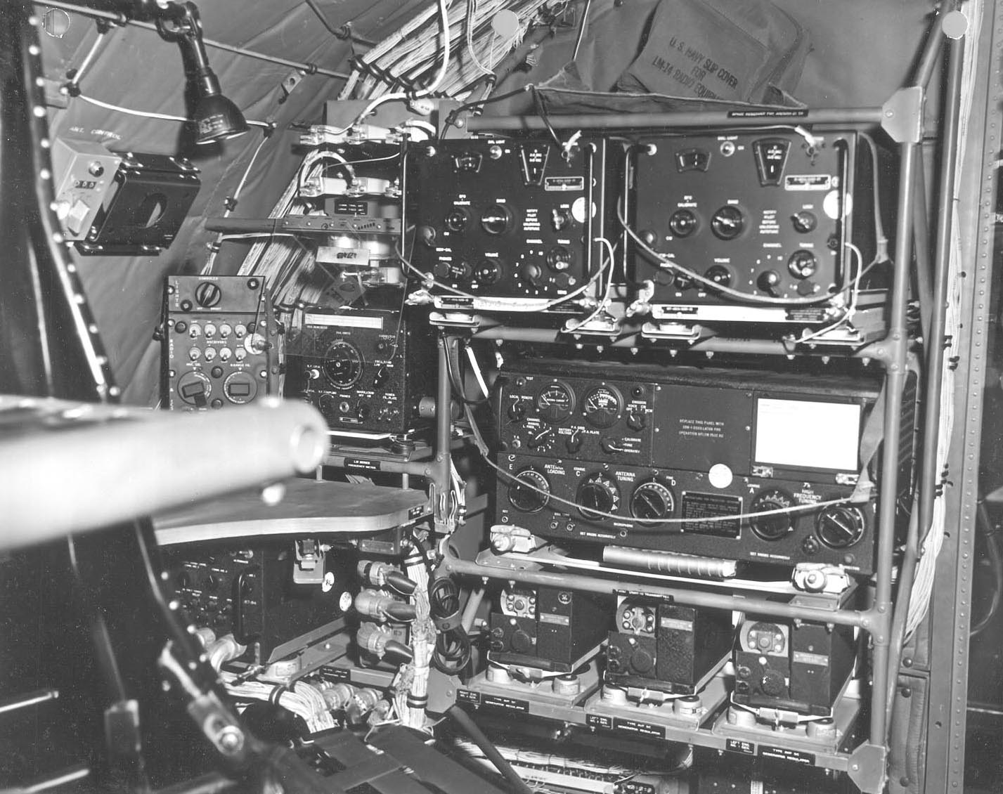
Here's a picture of them in the radio operating position of a military plane. (Photo is from this website: 51H-3.)

(Click on image to enlarge.)
Although I'm well familiar with the ART-13 transmitter (having disassembled one for parts back when I was in high-school), I've never seen (nor heard of) the R-105A receiver. It's the military version of Collins 51H-3 receiver, manufactured post-World War II (mine has a 1951 contract date). And, apparently, it was Collins first remotely-tunable receiver (tunable to 10 preset frequencies).

Although intended to be used on 10 preset frequencies, the receiver can also be tuned the "normal" way via a tuning-knob and band-switch on the front panel. Frequency coverage is 1.5 - 18 MHz in 6 bands, and modes are MCW (AM) and CW.

The R-105A is designed to be powered from 26.5 volts DC, and it uses an internal dynamotor (DY-34) to convert this voltage to 220 VDC for tube B+ voltage. If using the dynamotor, I believe an external power supply should be rated at 15 amps, 26.5 VDC.

My radio did not have the dynamotor installed. Instead, a previous owner had wired the B+ line to one of the spare pins on the back connector. My receiver's power requirements are:
  • 26.5 VDC (filaments/motor): 1.4A normally, 5A (or a bit more) when Autotuning.
  • 220VDC (B+): about 70 mA.

Here are some photos. Despite the relative shabbiness of the exterior, the interior is actually in nice shape.

(R105A, Top View)

(R105A, Bottom View)

(R105A, Right Side View)

(R105A, Left Side View)

Getting It Up and Running...


OK, the only documentation I had was a schematic that I downloaded from the web (see "Resource" section, below). The radio had no dynamotor, but the previous owner had brought B+ out to pin 18 of the rear connector. So I attached a 220 volt supply between pins 18 and 9 of the rear connector ("plus" to pin 18), and 26.5 volts between pins 17 and 9 ("plus" to pin 17). I attached a pair of headphones and an antenna, then switched on the power supplies, turned on the radio's front-panel switch, and...

Nothing. The dial-lights were lit, but I couldn't hear anything -- it was as if the receiver was dead.

I looked at the schematic again and noticed that the resistors in the cathodes of the RF Amplifier and the First IF Amplifier weren't grounded, but were instead going to pin 3 of the rear connector. Clearly they needed to be connected to something (such as ground), but what exactly should this be?

One of the websites I visited mentioned that, in CW mode, the front-panel Gain pot is used to control RF, rather than AF, gain. Hmmm...RF gain as in, perhaps, the cathode of the RF amplifier? Ah ha! A clue!

I noticed in the schematic that there was one section of the gain pot, R139C, that, when the radio was in CW mode, was connected to pin 20 of the rear connector. Could it be as simple as connecting pin 3 to pin 20 on the rear connector?

Yes! I connected these two pins together, applied power, and...signals!!!

There were still some issues, though. I could hear distortion on AM signals, and I could see that, for whatever reason, there was way too much gain -- so much so that the AF Amplifier was being driven into distortion for reasonable-level signals.

When I looked at the R-105A schematic that I had downloaded from the BAMA site, I quickly realized it did not match my receiver. In fact, that schematic is for the R-105 (non-A) version, and there are some significant differences, particularly in the Audio stages. So I traced out my receiver's circuit from the detector up to (but not including) the AF Amplifier. Here it is:

(Click on image to enlarge)

Regarding the distortion and gain issues, my primary suspects were the limiter and the AVC circuits. But I looked at my schematic and quickly realized there were some strange things in the design and that I had no idea how the limiter and AVC were really supposed to function. I poked around with a scope and DVM for a few days but didn't make any headway. What I needed was a good description of how these circuits were supposed to operate. Usually the military tech manuals contain some sort of theory-of-operation descriptions...it was time to try to round one up...

After a bit of searching, I found someone on the web that could sell me a manual reprint (see "Resources" below), and I ordered it. It proved to be quite useful...

The first thing that I discovered upon reading it is that pin 3 of the Limiter stage (V110), during normal operation, should be higher in voltage than pin 8 of the same tube (that is, both diodes are conducting). In my radio pin 3 was lower than pin 8 (despite the fact that the plate voltage of V105A was higher than V107A) and the diode of V110B wasn't conducting all of the time. Oh oh. Cap C133 looked fine -- must be a leaky 12H6. Unfortunately, I didn't have a spare tube in my tube-stash, so I made a solid-state replacement using an octal plug, two 1N4006 diodes, and an 80 ohm, 3 watt resistor (to mimic the tube's filament load -- I made this using 3 power resistors I found in my junkbox). The octal-plug was wired as follows:
  • 80 ohm resistor between pin 2 and 7
  • 1N4006 Anode to pin 3, Cathode to pin 4
  • 1N4006 Anode to pin 5, Cathode to pin 8
I plugged it in and...the voltages were now OK! (This mod should suffice until I can find another working 12H6 tube.)

But there was still a gain issue -- during modulation peaks, loud signals would flat-top at the output of the AF Amplifier. (Note: the front-panel gain control does not control the level of the signal fed to the AF amplifier, it actually controls the gain (via attenuation) right at the headphones. Thus it's reasonable to expect the AF amplifier to operate at a high level (to get the best dynamic range), but...it should never go into clipping!)

I spent quite a bit of time exploring the AVC and audio stages...was there too much gain in the audio? Was there not enough gain (or leakage) in the AVC circuit? Or...?

Although there's quite a bit of gain in the audio stages, it looked to me, from the component values and from what I was measuring, that the gain I was seeing was reasonable (and I reduced the gain of the AF driver as much as I could by setting R156, an internal pot, to its max value). I checked the AVC line for leakage or loss (the AVC line drives the grids of the RF amplifier the 1st IF Amplifier) -- it looked fine. Finally, after much poking around, the only explanation I could come up with was that there simply wasn't enough AVC control-voltage being developed to keep loud, highly modulated signals from clipping.

How could I develop more negative AVC voltage?

Looking at the schematic for the AVC circuit, it is is unlike any I'd seen before. Although there is a diode detector (V106A), this is only used to change the signal-level threshold at which the AVC begins operating, rather than, as is typical, developing the AVC voltage itself.

Instead, it is the second section of V106 (V106B) that actually develops the AVC voltage.

It does this by acting as a variable load on the AC-coupled IF signal (coupled to the tube via C123). If there is no AGC action, this IF signal sees R121 (1 Meg) as its load, and R125/C129C low-pass filter the signal across this load.

With small signals, the cathode of V106B sits at about 17 volts (this level is set by the voltage divider formed by R132, R122, and R133). For signals whose amplitude, at the plate of V106B, is less than 17 volts, the tube is in cutoff and, effectively, out-of-circuit. Thus the IF signal only sees R121 as its load, and because the IF signal is AC-coupled and R121 is unchanging, the AVC voltage, after the IF signal has been low-pass filtered, is 0 volts. (That is, the low-pass filter is essentially an "averager", and the average of an AC signal that is symmetric and centered on 0 volts is...0 volts.)

If the signal amplitude on the plate of V106B exceeds the voltage of the cathode, V106B begins to conduct (the amount of conduction is determined in part by the cathode-grid voltage: note that the grid is tied to ground). When the tube conducts, it acts like a finite-valued resistor in parallel with R121, the 1 Meg load resistance, and thus the load resistance seen by the IF signal (coupled via C123) is lowered. Because the tube only conducts on postive peaks, the IF signal sees this smaller load (and thus more attenuation) only during its positive peaks, but not during the remaining part of this signal's cycle. Thus, there is more attenuation for positive peaks than for negative peaks.

Because the positive peaks are attenuated compared to the negative peaks, the "average" of the signal is no longer 0 volts, but instead it is a negative voltage. And this is the AVC voltage.

V106A is used to lower the cathode voltage for strong signals to drive the AVC voltage more negative -- if the cathode is lower than 17 volts, the tube will begin conducting at a lower positive signal amplitude, and thus more of the positive peaks of the IF signal will be attenuated compared to the negative peaks, and thus the AVC will become more negative.

Essentially, V106A acts as a diode detector, detecting the IF signal coupled to it via C132 and developing a negative voltage which, when fed to the cathode of the second stage of V106 (via R123), subtracts from the 17 volts that is normally there (fed to the cathode of V106B via R126). C186 filters out the high-frequency IF signal, leaving only its negative audio envelope.

I needed to develop more negative AVC voltage during loud signals. After experimenting, I was able to get reasonable performance with this simple mod (which can be easily backed-out if one is a purist and wishes to keep their receiver in original condition) :
  • Parallel R123 (470K) with a 47K resistor.
  • Parallel C186 (470 pF) with a 4.7 nF capacitor.
This modification drives the cathode of V106B lower (on average) than occurs with the stock 470K resistor in R123 (because R123 is smaller, there is less voltage "lost" across it, due to the voltage-divider action that takes place with R126, and hence the cathode of V106B is driven lower (but never less than about 0 volts).

The change in the value of C186 matches the change in R123 and keeps unchanged the time constant of the filter formed by R123 and C186 (which filters out the IF frequency, leaving only the modulation envelope).

It seems to work well. In my listening tests (and measuring with a scope) there is certainly less distortion with the mod than without it.

That's it! Besides that, I haven't changed anything else in the receiver.

Other notes:

Althought the receiver really isn't designed for SSB use, it can be used in that mode, although tuning is a bit too fast.

The autotune is really very cool! (There are 10 channels you can preset.)

The IF is quite broad. It reminds me of using a Command Set receiver.

To Mute the receiver during transmit, add an SPST switch between pin 3 and pin 20 on the rear connector. This switch should be closed during receive and open during transmit.

With its octal-tube sockets and well laid-out design, the R-105A is a real pleasure to work on, especially when compared to typical ham boatanchors in which components are often buried under other components, making access difficult, if not impossible.


Resources:

Schematics here (BAMA site). Yes, they are small and difficult to read. But...they're the only schematics I could find on-line, and they're better than nothing at all. IMPORTANT NOTE: Although the BAMA site lists these as being schematics for the R-105A, they are actually for the earlier R-105 (non-A) version! There's a crystal rectifier detector shown in the schematic in lieu of a detector implemented with 1/2 of V105 (as my R-105A has). And V107 is shown as a 12SJ7 instead of a 12SL7. (By the way -- there's a mistake, too, in the schematics: they incorrectly show R107 connected to the same line as R111 (First Mixer's Cathode resistor). Instead, R107 should connect to B+. And I've no doubt there are other differences...)

AN/ARR-15A feature summary.

51H-3 Good information and a great picture of an ARR-15 / ART-13 pair aboard a P2V anti-submarine patrol bomber.

More pictures here.

Tech Manual: AN 16-30ARR15-3. [You can purchase reprints of this manual (as of 30 Oct 09) from WA5CAB.]

Rear-Connector Pin Assignments (traced from the schematic: click on image to enlarge):
And finally, a reminder that my later post (on improving the R-105's selectivity) can be found here.

Standard Caveat -- take everything I've written with a grain of salt. I could have easily made a mistake.

Thanks!

- Jeff, K6JCA

Sunday, October 18, 2009

KW Atlanta Transceiver


This cute little radio followed me home from last weekend's De Anza Swapmeet. It's an "Atlanta" transceiver manufactured by KW Electronics, Ltd., of Dartford, England.

KW Electronics manufactured radio equipment for the British market. I believe the Atlanta transceiver was their one foray into the American ham marketplace and was sold here back in the early 70's (although I must admit that I never heard of the company at that time).

As you can see from the photo, the radio isn't in "original" condition. There's a toggle-switch just to the right of the band-switch (discussed below). There's also an additional DC "accessory" connector in the upper left-hand corner of the Power Supply front panel, and I'm not sure if the meter is original, or not (I suspect it's not).

The radio uses two 6LQ6 sweep tubes in its PA (also compatible: 6JE6 tubes). PA final voltage is spec'd at 800 volts, but mine measures 700 volts in receive, and 650 when loaded in transmit mode (I don't know if the power-transformer is original, or if it has been replaced).

So, given the lower PA voltage, the output power isn't quite as high as I would have expected it to be, but it suffices.

On the receive side there can be "popping" on the starting edge of loud signals. The AGC is audio-derived (rather than being derived prior to the detector) and it has a rather slow attack time, so some amount of leading-edge popping is to be expected.

But, despite these small problems, overall it's a nice package.


Here are some of the issues I ran into getting it on the air...

1. No Power Switch -- Wired Permanently ON. There was a "goof plug" on the front panel, just to the right of the band-switch. I opened up the radio and discovered that, at one time, there had been a power switch mounted to the back of the AF Gain potentiometer, but it had been removed by someone. Apparently they then drilled a hole in the front panel for a toggle switch, but by the time the radio got into my hands the toggle switch had been removed and the radio wired to be permanently On. I removed the "goof plug" and put a toggle switch into the existing hole.

2. Very low speaker volume -- someone had added a cap in series with the speaker and also ran a separate ground for the speaker from the radio to the power-supply unit (which they left unconnected). Why, I don't know, but I suspect they made these two mods to reduce speaker hum. But the cap was much too small, only 1 uF or so (thus presenting a very large series-impedance at AF frequencies). I removed it and wired the seperate ground to the speaker, and it works fine now.

3. Intermittent receive signal strength. Receive signals would sometimes be loud, and other times weak. If I touched the rear panel, I could make them fluctuate: clearly an indication of a bad connection somewhere. After hunting around, I finally found a lose connection at the bottom of L2 (inductor in the ouput pi-network). A very awkward location. Luckily, I had a very narrow soldering iron, so I could get to the bottom of the coil and repair it!

4. Low Power Output -- only 50 watts or so. I brought the power up by peaking transformer T1 per, I thought, the instructions in the manual (they're a bit ambiguous). However, carrier suppression was now terrible. I was able to get better carrier suppression, but I had to change T1's alignment procedure. Here's what I did:
  • T1 has two cores. Move the core closest to the chassis all the way to the chassis-side of T1. Let's call this the "bottom" core.
  • Transmit and insert some carrier, then adjust the top core for max TX signal.
  • Stop transmitting, and then adjust the bottom core for max RX signal.
  • Repeat, if necessary.
5. Poor Carrier Suppression. First, I adjusted the frequencies of the two carrier-oscillator crystals so that the bandwidth in both modes (when operation, say, on 80 meters) was close to identical (BW about 300 - 3100 Hz, measured using a white-noise source fed into the mic inputand a spectrum analyzer on the output). This put the carrier level for both sidebands at about the same level (when viewed on a spectrum analyzer). Then, with the Carrier Balance knob pointing straight up, I adjusted C114 for minimum carrier in both sideband modes. Then use the front-panel pot for fine-adjusting. You might need to do this several times before getting a good null. (Note, I'd tried to null carrier by nulling with the pot first and then adjusting C114. I could never get good suppression this way.)


Ongoing Problems...

1. Carrier does not remain suppressed. Don't yet know why...
(Update, 25 October 09: While poking around, I discovered that the two 100K resistors in the balanced modulator (7360) bias-network circuit had drifted an enormous amount -- one measured 232K, the other measured 335K! I ran a quick calculation (using the measurements of voltages that I'd made) and discovered that, if they had been 100K resistors, they each would have been dissipating more than 0.5 watts. Not good (given that they're 0.5 watt resistors), and perhaps the cause of the enormous change in resistance value. I've replaced them with 100K ohm, 1 watt resistors. Brief testing shows promise -- the carrier suppression seems to be a bit more in line, now.)
2. Noticeable distortion on very loud receive signals. Surely AGC related, but I don't yet have a fix...


Notes:

1. Voltage Chart Errors. Take the voltages listed in the manual's "Voltage Chart" with a huge grain of salt. Some are clearly wrong, such as the voltage on V16 pin 6. There is no way it can be 210 volts -- it comes, via a resistor, from the 150 volt regulator!

Similarly, some of the "positive" voltages are actually negative (unless I am really screwing up my measurements!).


Resources:

Yahoo Group: KW-Radios This is a great resource for schematics, manuals, etc.

KW Atlanta Photo: Atlanta

Thursday, October 15, 2009

Yaesu FT-1000D AGC Mods

Some years ago I purchased an FT-1000D. After using it for awhile I began to notice subtle distortion on SSB receive audio that, over time, I found more and more annoying.

The distortion artifacts were subtle but noticeable. They sounded like a slight "crunching" or "crackling" sound (very noticeable when someone says "ahhh."), and could be made to stand-out (when looking for its presence) by rotating the "Shift" knob to accentuate high frequencies. With the shift in its normal position, the distortion was still present, but it tended to be masked (in most cases) by the higher level of the voice signal.

(One quick test I use for locating the cause of audio distortion is to reduce a receiver's RF Gain. If the audio sounds clearer with less RF gain, then, in my experience, there's a very good chance that AGC action is creating the distortion.)

I reduced the FT-1000D's RF Gain. The the audio sounded clearer. Ah ha! There was a very good chance that the distortion, therefore, was related to AGC action, and so I started experimenting...

My main concern was SSB operation (for which I usually use either SLOW or MEDIUM AGC rates). Looking at the schematic, I noticed that there was a 10K resistor (R2140) in series with the 2.2 uF cap used for Slow AGC. Shorting-out this resistor reduces SSB distortion. But it will distort the CW envelope. My feeling was that I never use Slow AGC for CW, so this was an acceptable compromise to make.

Even the 4066 analog switch introduced some distortion artifacts (per its datasheet, its resistance is about 500 ohms for a 10V supply voltage). I replaced this analog switch with a relay, which has a much lower "ON" resistance.

I also replaced the analog switch used for switching in the MEDIUM AGC circuit (the 0.47 uF cap) with a relay. Experiments for FAST and MEDIUM AGC settings revealed that, for CW, a 30K resistor actually worked better than the original 10K ohm resistors used for these time-constants. So I added a 30K resistor (replacing the two 10K resistors) that is common to both the FAST and MEDIUM caps (0.22 and 0.47 uF).

However, the 30K does produce distortion artifacts on SSB. So I decided to compromise: only for strong signals is the 30K ohm resistance switched in -- for normal or low-level signals, the resistance is very low. (For low-level signals, the AGC line sits high. This turns on a 2N2222 which in turn shorts out the 30K resistor. For strong signals, the AGC line is driven lower, until, for very strong signals, it drives the 2N2222 into cut-off (threshold set using the two series-diodes attached to the base), which then places the 30K back into the circuit.)

I found that the 30K also increases distortion on AM signals, so I also short it out for AM operation. (Therefore, it is only present for strong CW, SSB, and, I suppose, FM (it has no effect on FM)).

Here's my original markup of the FT-1000D schematic:
(Click on Image to Enlarge)


Here's a drawing that might be a bit clearer...

(Click on Image to Enlarge)


Notes:

1. If one would like to keep the changes simple and not incorporate all of the mods that I made, I would recommend the following two modifications:
  • Short out R2140 (10K ohms: Slow AGC.)
  • If you use Medium AGC for SSB, then also short out R2141 (10K ohms: Medium AGC. But note that this may create some fuzziness on CW signals.)
2. While reviewing my notes from 2003, I discovered a mention in my lab notebook of the addition of a Schottky diode across the 1.5M resistor (cathode connected to the RF GAIN side of the resistor) so that, as RF Gain is turned down, the AGC follows with little delay (otherwise there could be a long delay for the audio level to catch up with the control position. But I don't show this diode in my final schematic. I don't know if it's actually there, or not, and I'm not about to reopen the FT-1000D to find out.

3. I used Clare DSS41A05 Relays.

4. Audio envelope testing was performed by modulating the RF signal from an HP 8640B (in AM mode) with a pulse generator (100ms pulse, rep rate of 1 second, 2 ms rise/fall, 1.4v peak, -1.1v DC offset). The AGC waveform was monitored @ TP2005, and the audio envelope monitored at the headphone jack.

5. Diodes are in series with the base of the transistors to ensure that they fully turn off when the control signals go low.


Important note:
I made these modifications to suit the style of operating that I prefer (SSB ragchewing). These modifications may not be suitable for your style of operation. So, if you're also experiencing annoying distortion, please consider these mods to be a starting-point for your own experiments in improving the performance of the 1000D.

Tuesday, October 6, 2009

Central Electronics CE 100V Transmitter

My adventures bringing a CE 100V back to life!

A number of local hams have Central Electronic 100V transmitters, and on occasion I've joined them during their ragchewing roundtables on 80 meters (sans 100V on my part). I enjoyed the sound of the radio as well as its styling, and I thought it might be nice to have one of my own. And thus began my search for a 100V.

I finally found one that a local ham was selling on Ebay. I made a bid...and won it! Fortunately, because the seller was local, I was able to save shipping charges (it is a heavy radio!) and pick it up myself.

When I got it home, I discovered the radio, besides having extensive cosmetic issues, also had operational problems, and I put it to the side while I worked on other projects that were less daunting than tackling the 100V appeared to be.

Finally, I decided to bite the bullet and get the 100V on the air. First thing to do...pull it out of its cabinet and then get to work...

The radio is a marvel of design, and arguably represents the high-water mark of amateur radio transmitter design of the 50's. Which translates into a radio that is large, heavy, and complex (26 tubes!).

(Top View, with VFO Assembly removed)


(Paging Doctor Frankenstein!)

When I looked inside the actual radio, my heart sank...the chassis wasn't dirty, it was oxidized. I believe it must have originally been plated, and this plating had turned an ugly grey color. And in some places, actual rust had appeared!

(Typical oxidation/corrosion on this radio. Labels on the back panel and on the chassis are essentially unreadable.)


(Despite the terrible shape of the chassis, the front panel actually looks pretty good!)

My VFO was very difficult to turn, and felt "lumpy". Per the Tusa notes (well worth a read) on the 100V, I decided to remove the VFO assembly and take a look at what might be going on...

(Note: the VFO assembly is actually fairly easy to remove. You do not need to drop the front panel! Instead, follow the procedure in the Tusa notes (although please note that for step 7, you should unscrew the two bottom mounting posts from the VFO assembly, not from the front panel)).

After I'd removed the VFO assembly, I was curious to know how it looked inside, so I removed the back cover. Whoops! Chunks of foam (and foam bits) tumbled out. Looks like Central Electronics used this foam (3/8 " thick) to act as an insulator to minimize temperature variations within the can. And after 50 years, it was disintegrating.

(Disintegration of the insulation foam in the VFO Assembly!)

I happened to have an old mouse pad lying (1/4" neoprene), so I cut it up and glued it to the inside of the can with some RTV cement. Voila!

(Old mouse pads have many uses, such as...new insulation!)

Now to attack the difficult-to-turn VFO. The Tusa notes recommend repacking the bearings, but from the instructions I'd read (and from the stories I'd heard), it sounded like a real nightmare.

Instead, I decided to see if a shot of WD-40 into the bearings would help to loosen up the old grease...

I held the VFO so that the knob was pointing toward the floor, then applied a quick burst of WD-40 into the "well" (see photo below). The bearings are below this well, and, by holding the knob towards the floor, I hoped the WD-40 would flow down into the bearings.

It seems to have worked. The mechanism turns much more easily now. Sure, I probably ought to repack the bearings (because the viscosity of the grease might give it a bit "smoother" feel). Maybe next year...
(Click on image to enlarge.)

While I had the VFO out of the radio, I was curious to learn how the VFO tracking mechanism worked...

As the VFO frequency is adjusted, the VFO's lead screw moves a core in and out of the main VFO coil, thus changing the oscillator frequency. But there is a secondary adjustable coil, too, whose core is attached (via a rod) to a right-angle bracket that can pivot. This rod moves in and out of the secondary coil according to the height of the "VFO Corrector Adjustment Screws," and allows small corrections to be made to the VFO frequency as the the user tunes over the 1 MHz-wide range of the VFO.

You can get an idea of how the mechanism works from the two photos below:
The lead screw moves the frequency correction assembly (consisting of the screw run through the block) along either direction of the lead screw (depending upon whether the frequency is being adjusted up or down). A rod runs over the bottom of these screws (shown bottom-up in the photo above), which in turn causes the metal right-angle bracket to which it is attached to pivot.

Attached to the other end of this right-angle bracket is a rod which drives the core of the secondary coil in or out, thus correcting the frequency. In the photo below you can see both the larger main coil (on the same axis as the lead screw) and the smaller secondary coil below it (only a couple of turns of this coil are visible).
Pretty clever!

A note about the frequency correction adjustment. I would recommend that you start at the end of the VFO that has the largest "positive" (rather than negative) delta from the dial frequency. In other words: if the offsets at either end of the dial are both positive, start at the end that has the largest positive delta. If both of the offsets are negative, start at the end that is closest to the dial frequency, and if one end is positive and the other negative, start at the positive end.

"Zero" your dial at this frequency by moving the black line on the clear plastic to overlay the "0" on the dial (there's a screw a few inches below the VFO knob that let's you do this). Then, moving the VFO in 500 KHz increments, adjust the frequency using the "VFO Corrector Adjustment Screws" per the Tusa Consulting note on VFO Recalibration.


Problems that I've run into:
  1. Meter not working. No movement, at all. I opened up the meter and discovered that one of the "spiral springs" that attach to the armature had opened up. It was a real pain to repair, but repair it I did. (By the way, my meter is about 1 mA Full Scale, and has a resistance of 47 ohms). I also added a pair of diodes (1n5818) hooked antiparallel across the terminals of the meter (to protect the movement from burning out), as well as a 0.1 uF cap -- if you add the two diodes you must include this cap, otherwise your meter may read low in the "Watts" position.
  2. VFO Sticking/Hard-to-Turn (See discussion above)
  3. VFO Not Tracking (See discussion above)
  4. Lack of the -120V Blocking Bias in STBY mode. A 1uF/200V electrolytic cap that was attached to this line (via a 10 ohm resistor in the power-supply section) was shorted to ground. (Note: neither this cap, nor the 10 ohm resistor, appear in the schematics). These parts were probably added to slow-down the transition between STBY and Transmit. I didn't have a 1uF with a high enough voltage rating in the junkbox, so I instead used a 2 uF cap.
  5. Inability to Null Carrier in Sideband Modes. The meter would remain pegged to the right in Null mode irrespective of any adjustments I made to the two Carrier Balance knobs. I measured the forward-voltage of the four original germanium (CK715) diodes in the modulator plug-in module, and the voltages varied wildly (from 0.234 volts to 0.632 volts). I replaced these with HP 5082-2063 (Schottky?) diodes that I had in one of my parts' bins (their Vf was 0.34 volts, and matched within millivolts for all 4 diodes). Works fine now.
  6. Wattmeter: Reads too low, and cannot adjust far enough. Resistance values had drifted over time, and one of the 100 ohms resistors had drifted to 109 ohms. Replaced with 100 ohms, and now can adjust with the pot (although it's almost at its limit).
  7. RF Ammeter: Reads too high, and cannot adjust far enough. The resistors have apparently drifted. The voltage-divider resistors are in an extremely awkward location, so their replacement is very difficult. Instead, I added 120 ohms in parallel with R147/R148, and that brought the voltage into range to allow correction using the pot.
  8. No X-Axis movement on Monitor Scope. Replaced V21 (6U8A)
  9. Low-frequency Noise in Audio, Eventual Loss of Sideband Suppression. I traced this to a leaky cap in the audio phase shifter module -- one of the symptoms was a high DC voltage at an output (pin 8) of the phase shifter. Cap C130 was leaky (but the leakage couldn't be measured with a DVM) -- I replaced this 4711 pf mica cap (actually measured 4739 pf) with 4731 pf consisting of a 4300 pf mica and a 470 pf mica in parallel. (Update: I've discovered that this problem is discussed in the 100V article by Charlie Talbott, K3ICH, in the August, 1996 issue of Electric Radio, and I've implemented one of his mods, which is to insert a 1uF, 400V cap betweenV7 pin 1 and the phase-shift network PS-2 socket's pins 2 and 6 (to isolate C128 and C130 of the phase-shift network from the B+ voltage on V7's plate)).

With these issues resolved, I've deemed the 100V ready for the air:

The 100V in its operating position!

Although the 100V is now up and running, there are still...

Problems I've yet to resolve:
  1. 8 MHz Oscillator cannot be adjusted to be exactly 8.000 000 MHz (it remains too low). Even with the adjustment cap at minimum value.
  2. FSK Adjustment does not span 100-900 Hz. Instead, it only seems to have a range of about 150 Hz.
  3. PA "Idle" Wattage (in SSB Xmit, no voice) should be in the range of 60 watts (per the recommendation of others) -- mine is more around 30 watts. (Central Electronics added adjustment pots for both the driver bias and the PA bias adjustment to their 200V transmitter, but these parts are not in the 100V, and to add them involve more surgery than I'm willing to undertake at the moment).

Other notes and Comments:
  • The schematics can be inaccurate! I've found additional parts, and I've found parts missing, when comparing the actual circuitry to the schematic.
  • Tusa Consulting has a number of notes on the CE 100V and 200V transmitters. You can find these notes here.
  • A previous owner had replaced the two batteries internal to the Speech Limiter module with two AA-size alkaline batteries, and had mounted their holder on the outside of the Speech Limiter's case.
  • To get at the tubes and adjustments beneath the fan in the audio section, just loosen the transformer screw and tilt the fan bracket up...

  • Some other useful data...
100V I.F. Mixing Scheme
(Click on image to enlarge)

Some manual copies have impossible-to-read voltage charts. Here are clearer copies (thanks to Jon, K6JEK).

Tube Voltage Chart
(Click on image to enlarge)

RF Voltage Chart
(Click on image to enlarge)

Articles on the 100V in Electric Radio magazine:
  • "Restoration of the Central Electronics 100V," Dennis Petrich (K0EOO), Electric Radio, Number 20, October 1991.
  • "Observations on the Central Electronics 100V & 200V," Charlie Talbott (K3ICH), Electric Radio, Number 88, August 1996.
(There may be additional articles in Electric Radio. These are the two that I've found.)


Phase Network Simulation [11 March 10]:

I ran a SPICE simulation on the CE 100V's Phase Network and compared the two outputs. Here's the plot (and the schematic):

(Click on image to enlarge)

The solid line is amplitude, while the dashed line is phase.

Sideband suppression (in dB) versus phase error can be calculated with the following expression:

-20*log10*|tan(phase-error/2)|

A phase-error of 1 degree (from the ideal phase-shift of 90 degrees) will result in about 41 dB of sideband-suppression; a phase error of 2 degrees: 35 dB; while a phase-error of 10 degrees will result in only about 20 dB of sideband suppression.

(Note: I haven't included in this simulation the small-signal resistances presented by the grids of the tubes that the phase network output drives (I don't know what they are). For ease of calculation, I've assumed that they're infinite. Also, because I don't have any SPICE models for tubes, I just used a transistor as the driver.)

[LTspiceIV, the program that I used for my simulations, is free, and it can be found here.]


Standard Caveat!


I may have made a mistake in any of the above, so use at your own risk!

Monday, September 14, 2009

PRC-47 Modifications


[2 December 2010: Added an Addendum to the "Replacement of the Switching Supply Power Transistors" section, below.

8 February 2011: Added another Addendum at the very end of this post.]


The PRC-47 is a Vietnam War era SSB transceiver designed to operate from 2.000 to 11.999 MHz in 1 KHz steps. It is USB only, but can also operate CW or FSK, and it's designed to be powered by either a DC supply (from 24 to 28 VDC) or a 115 VAC, 400 Hz supply.

Transmit power (into a 50 ohm load) is rated at 100 watts PEP (High Power Position) or 20 watts PEP (Low Power Position).

Here are some pictures of my PRC-47:

(Click on Image to Enlarge)

Note the modular construction with plug-in modules...


...And an easily accessible chassis:


Replacement of the Switching Supply Power Transistors:

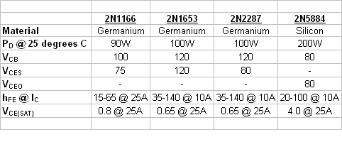
I've had several PRC-47 transceivers in which the two 2N1653 transistors (used to convert the 24 VDC to 24 V "square-wave" AC) were bad. I replace these two transistors (Q1 and Q2, on the chassis, just under the faceplate) with more modern 2N5884 transistors, which seem to work just fine.


[Addendum, 2 December 2010]

The original transistors used for Q1 and Q2 in the Switching Power Supply are Germanium, and are either 2N1166, 2N1653, or 2N2287 transistors (I have one Tech Manual that specs the 2N1653, and another which specs the 2N2287, and others have told me that the 2N1166 is also used in some units).

Germanium transistors are difficult to find, so, to replace the original "failed" transistors, I chose a more common Silicon PNP transistor. The 2N5884 which I use is not a perfect match for the original transistors, but it's close. Here's a comparison of the specs of the three original transistors (from
the fourth edition (1969) of Motorola's "The Semiconductor Data Book") versus the 2N5884 (from ON Semiconductor's website):


It's worth noting that diodes CR1 and CR2 in the Power Oscillator are there to limit the collector-emitter voltage of transistors Q1 and Q2 (the 2N1653 transistors) to 26.5 volts, so, assuming the diodes are still OK, the 2N5884's max rating of 80 volts should provide plenty of headroom. (I haven't made any measurements to verify this, though).

If anyone is concerned about breakdown voltage, you might try experimenting with the MJ15004 transistor -- it's rated to 140 VDC. However, its Ic (continuous) rating is only 20A, versus 25A of the 2N5884, so there's a tradeoff. Personally, I'd go with the 2N5884.

By the way -- the higher Vce(sat) of the 2N5884 (or MJ15004) might result in a lower plate-voltage to the PA tube (because the voltage swing at the primary of T1 will be lower (26.5 VDC - Vce(sat)), and thus lower output power. I haven't verified this, but if you find it to be the case, you can try bumping up your DC input voltage to, say, 28V, to help counteract the swing limitation due to the higher Vce(sat) of the Silicon transistor.

(And whichever transistor you use, please report back with your results!)


PTT Not Working?

If PTT doesn't work on your radio, check the following:
  1. Ensure that CR18 is installed in the AF Amplifier Module (I use a 1N4148).
  2. Ensure that the "PTT" wire (green, in my set) is connected to J2.11 on the chassis (this is the DB-25 jack into which the AF Amplifier Module plugs). If not connected, you might find it tucked to the side.
(Note: It's possible that very early versions of the PRC-47 don't have a PTT function, but are VOX only. I have an "Advance Copy" of TM 11-5820-509-35, dated November 1963, which shows no connection to pin 11, nor the existance of CR18 in the schematics (I presume the set, at that time, was VOX only). However, my later (electronic) version of the manual, dated July 1974, shows these connections.)


LSB Modification:

A radio which only operates USB in the range of 2 to 12 MHz is of limited use to a radio amateur. However, the PRC-47 can be easily converted to LSB operation. To do this, you need to replace the mechanical filter in the IF module (which happens to be a 500 KHz, LSB filter) with a 500 KHz, USB filter. And voila, you'll have LSB.

Here's how I make this modification:
  1. Remove the Amplifier-Modulator module from the radio and remove its covers.
  2. Remove the mechanical filter and replace with a Collins F500-Z4 (or equivalent) filter.
  3. Apply +20V to P4 pin 3 (this will supply power to the module) and the 20V return to the module case. (I find it easiest to attach +20V to the far left side of L9.)
  4. Set a signal generator to 501.5 KHz and apply the signal to J3.
  5. Measuring at J1 (with either a scope or spectrum analyzer), adjust the generator's level so that you see a signal (but don't overdrive the module), then...
  6. peak the measured signal by adjusting the two variable caps, C15 and C17.

AGC Modifications:

In my opinion, the "stock" PRC-47 AGC design results in severe and unnecessary distortion of the receive audio signal. One of my first goals was to attempt to improve the quality of the receive audio. In trying to fix the AGC I'd find a solution to one problem, only to then have another problem (previously hidden) reveal itself to me. And so the modifications, like coral, grew by accretion. Thus, they may not all be necessary (because a later mod may actually cancel the need for an earlier mod), but it would take much more time to determine which mod is irrelevent and which is not, so I've left them as I've implemented them.

First, a bit of background...the PRC-47 AGC is audio derived and results in two AGC signals: -AGC (which controls the gains of the the input RF preamp tubes) and +AGC, which controls the gain of the IF stage.

For SSB operation the PRC-47 has, in my opinion, an AGC decay time which is much too fast. The +AGC line is the dominant actor for normal SSB signals, and thus, to increase the decay time of C42, I changed R74 from 22K to 220K, and then added an emitter-follower (2N2222) to keep C42 from being loaded by successive stages.

I found, though, that when I did this, signals at normal "everyday" signal strengths sounded good, but very strong signals still distorted. A bit more investigation revealed that, with very strong signals, the +AGC signal was being driven so high that it was driving the IF stage transistors (Q2 and Q3 in the Amplifier-Modulator module) into cutoff!

I fixed this by limiting the the level to which the +AGC signal can go with a 13V zener (which, in my radio, results in a clamp voltage around 12.6 volts). Not elegant, but it keeps the IF transistors out of cutoff, and the -AGC signal (which kicks in at higher levels, and which is not limited) performs the AGC function for those very loud signals. (By the way, the 390 ohm resistor that I added between the emitter of the Emitter-Follower and the +AGC line limits current when the zener is driven into conduction, and the 22K provides the original resistance-to-ground as seen by the Amplifier-Modulator module and provides a necessary bias path for the transistors in the Amplifier-Modulator module.)

(I actually use the signal at the emitter of the emitter-follower to serve an "S-Meter" function (described later) because, at the emitter, the AGC voltage isn't clamped by the zener. Thus the S-Meter covers a wider voltage range than it would have otherwise if I'd used the +AGC signal. This signal (from the emitter-follower's emitter) I call "Buffered AGC+", and I connected it to a spare pin on the module's DB-25 plug (pin 12) so that I could then route it over to the meter circuitry located elsewhere in the chassis.)

Another problem I encountered: after releasing PTT, there was increased noise from the speaker (lasting for about a second) until the AGC stabilized the signal level. When I monitored the voltage across C42, I'd see its voltage actually drop momentarily (thus increasing receiver gain) when I transitioned from Xmit to Receive, and then it would recover. Removing C35 eliminated this noise burst.

After I had removed C35, I discovered that sometimes I'd lose output power during xmit. When this occurred, I noticed that the +AGC voltage was rising (and thus cutting off IF amplifier gain). I suspected that noise on the +26VDC line might have been affecting AGC during transmit (because C35 was removed), and I modified the circuit to use the +20 VDC line instead. Note that this required paralleling R59 with a 33K resistor to keep the junction of R59/R55 at around 8 - 9 V during transmit.

Essentially, during transmit relay K1 applies 26 VDC to the VOX line. This turns on a 2N3904, which in turn switches on a 2N3905 which connects +20 VDC to R59 (less, of course, a Vce(sat) voltage drop), rather than the original 26 VDC.

Another issue: during transmit, because of the newly-added 2N2222 emitter follower, the voltage across C42 can drop to near 0 volts. Then, when switching back to receive, it's possible to have a "pop" on the attack of loud signals because this low voltage causes the gain to be too high.

I fixed this by clamping the voltage across C42 during transmit: a 2N3904 transistor turns on (during transmit), which forces the voltage across C42 to be about 3.8V (the 3.8V comes from a 3.9V zener). Then, when we transition back to receive, there's less of a difference between initial receive gain and the required receive gain. (We could actually have used a zener with a bit higher voltage (nearer, say, 4.8 to 5.4 volts), but 3.9 volts seems to work fine.)

Here are some voltage measurements on my PRC-47 with these mods:
  • Receive, no antenna connected: V(C42) = 0.4Vdc V(Buffered AGC+) = 5.4Vdc
  • Receive, 80 meters, w/antenna and atmospheric noise: V(C42) = 9.4 Vdc V(Buffered AGC+) = 8.9Vdc
  • Transmit: V(C42) = 3.8 Vdc V(Buffered AGC+) = 5.4Vdc
Here's a schematic showing these AGC Mods.

(Click on Image to Enlarge Schematic)

Here's how the implementation looks:


Adding an S-Meter:

Normally, the PRC-47's meter doesn't move when the radio is in Receive mode. I thought it might be nice to have some sort of indication of relative signal strength (having a "dead" meter always seems a bit unnatural to me). If you don't mind a meter that's uncalibrated and non-linear, then here's a simple mod you can make.

It does require using a spare pin on the AF Amplifier module to run a "Buffered AGC+" signal to the outside world (and a wire added from the DB-25 jack (J2 on the chassis) to the new components mounted elsewhere on the chassis (see photo below for component location and mounting -- I used pin 12 of the DB-25 (J2) for this new signal). You can find a description of this "Buffered AGC+" signal above, in my AGC mods. (A "buffered" agc signal is used to drive the meter in order to keep the meter from loading the AGC cap: additional loading would worsen agc performance by shortening the agc decay time.)

I simply "diode-OR'd" this new AGC voltage with the existing "Xmit Signal Strength" signal. "Diode-ORing" simply means that whichever of these two signals has the highest voltage level will be the signal which controls the meter reading.

During Receive, the "Buffered AGC+" signal runs from about 5.4V (no antenna attached) to around 17.7 volts max (for strong signals). And during xmit this signal is at 5.4 volts. The 7.5 volt zener keeps the meter at 0 when there's no antenna attached (because 7.5 volts is greater than 5.4 volts, the zener doesn't conduct), and there's a couple of extra volts of head-room to keep the needle at a reasonable (left-side of meter) deflection when receiving normal atmospheric noise. And because this zener doesn't conduct during TX either, only the Xmit Signal Strength signal feeds the meter during TX.

Xmit Signal Strength is actually a fairly low level signal (if I recall, from my measurements it's about 250 mV max), and thus I used a Germanium diode (1N34) for this side of the diode-OR because of this diode's low turn-on voltage.

The 200K resistor limits the current to the 50 uA meter so that, at the strongest receive signal levels, the meter is just at its maximum deflection.

Here's the schematic:

(Click on Image to Enlarge Schematic)


And here's its implementation. I added a terminal strip for the additional components.


Transmit Audio issues:

The PRC-47 transmit audio leaves a LOT to be desired. It has an audio "compressor" which will distort the signal. Carbon mics can sound crummy. An inordinate amount of crud from the switching supply is coupled into the signal, manifesting itself as an underlying "whine" sound.

The conversion of the 24 - 28 Volt DC source to AC (actually, a square wave), which is required to generate the other voltages that the radio requires, unfortunately results in nasty switching artifacts that appear everywhere throughout the radio (on the +20VDC line (and other signals)). The ultimate result? Whine on the TX audio.

I've worked for many frustrating hours trying to minimize this whine. I've had some success, but I've never been satisfied. Because I use an "amplified"D-104 as my mic, I finally resorted to a simple solution: apply even more gain to the D-104 signal, EXTERNALLY (so that it's much louder than the internally-coupled noise), and bypass the radio's internal gain stages (into which the noise was being injected and amplified). This doesn't completely eliminate the noise, but the noise does seem to be much less and just about tolerable.

During my attempts to reduce this whine, I tried any number of fixes. Some seemed to improve things, such as the addition of 0.01 uF from the "CW Key" signal to ground (I mounted this on the back side of the middle board in the AF Amplifier module). But many of the mods I tried had little effect.

(One likely area of coupling might be the "Mike Input" wire. This wire runs from the Mic Connectors on the front panel to J2 pin 25 on the chassis (the AF Amplifier module's connector), and during its run from the front panel to J2.25 it's bundled together with quite a few noisy wires in a wiring harness. Thus, noise coupling onto this wire is certainly a very real possibility. One mod I'd like to try to reduce this possible coupling is to replace the wire with a shielded wire (e.g. coax). Unfortunately, on my radio, the Mic Connector pins to which this wire connects are difficult to get to. So, I'm leaving this for another day...)

Here's the External Mic Preamp which I built to drive the PRC-47 (I needed more gain, even though I'm using an "amplified" version of the D-104 mic):


And here are the mods I made to the mic amplifier side of the AF Amplifier module:

(Click on Image to Enlarge Schematic)

(I recognize that this solution really only suits my particular situation, and it is of little use if one wants to use a carbon handset or mic with the radio. So I encourage readers to experiment and discover what works for them. One tip I can give -- a friend, Dick (W1QG), replaced R2 (47 ohms) with a current source (about 600 uA), and also added emitter degeneration to Q1 and Q3, to lower the gain of both of these stages. This apparently helped out when using a carbon mic.)


A note on how I adjust the "MIC AMPL GAIN" pot (R27) on the AF Amplifier module...

Adjustment of this pot is described in section 3-26 of the Tech Manual (TM 11-5820-509-35). I'm lazy, so rather than attach a generator to the mic input, I adjust R27 using the TUNE signal (when in Tune Mode) so that it measures 3.5 vpp at the measurement point (see section 3-26.b). Then, once I have R27 set to 3.5vpp for the TUNE signal, I adjust the gain of my EXTERNAL mic preamp to also give 3.5 vpp at the same measuring point (for voice peaks). (Note, diodes CR5 and CR6 act as limiters, and they limit both the TUNE and the mic's audio signals -- if you're using an external mic preamp and you set its gain too high, you'll grossly clip your audio signal, which can add distortion. The TUNE signal, by the way, isn't a nice sine-wave, but is clipped by CR5 and CR6.)

If the radio is already buttoned up, I adjust the gain of the External Mic Preamp to give the same envelope peak voltage on the RF output (monitored with a 'scope) that I get in the TUNE position.


Curing that "Donald Duck" sound on Sidetone:

During Transmit the PRC-47 can insert a small amount of the TX audio back into the receive path so that operators, while transmitting, can hear themselves talking. This audio is called "sidetone", and its usage comes from the telephone world, where it was found (allegedly), that if people heard themselves in their telephone handset's earpiece while they talked, there was less of a tendency for them to yell into the mouthpiece.

Unfortunately, the PRC-47's sidetone signal can sound very distorted (I liken it to "Donald Duck"). The cause seems to be an audio envelope that appears on the "Sidetone Gate" signal during transmit. I improved this by adding a 4.7 uF cap from the "Sidetone Gate" line to ground in the AF Amplifier module (cap '+' goes to ground, cap '-' goes to Sidetone Gate).

If using an external speaker in lieu of a handset (which I do), sidetone can be quite annoying, so I also turn the sidetone gain potentiometer (R46 on the AF Amplifier module) all the way down.


Other Notes:

1. Extender Cables.

When working on the PRC-47, it's nice to have a set of extender cables that will let you remove modules from the chassis for debugging/experimentation, yet allow them to remain attached. Cables for this purpose actually exist, but are difficult to find. However, it's easy enough to make one for the AF Amplifier module (which uses a DB-25 connector). Here's the one I made (shown in use):


2. Documentation:

Get the latest version of the Tech Manual (TM 11-5820-509-35). The one I have is in electronic format (PDF), dated July 1974. Various modules have been modified over the years (from the initial design), and it's worthwhile having the schematics for the latest designs (Chapter 1 lists the various changes that have been made to the radio since is inception).

However, there is one caveat regarding this manual: there ARE errors! The text was (apparently) read in via OCR, and the usual goofy OCR mistakes are the result (I guess proof-reading was either sloppy or non-existant). Also, the schematics can have errors. I've run across a few, but, fortunately, not many.

(Also -- I always keep a lab notebook nearby in which I jot down notes, modifications, and measurements as I'm going along. It's a habit I got into as an engineer and it helps tremendously when, years later, you're looking over a schematic and wondering, "Why the hell did I do that?" Which is exactly what happened to me when I started writing up this post on the PRC-47 -- many of these mods were made six years ago, and it was no longer clear to me why I'd made some of them. Fortunately, a quick glance through my lab notebook quickly resolved any questions that I had.)


3. Pot Settings.

I usually set the following pots as follows:

On the AF Module:
  • R46 (Sidetone Gain): Full CCW
  • R52 (AGC Gain): Full CW
  • R54 (Rcvr Gain): Set per manual (section 3-22). Or use your ear.
  • R27 (Mic Ampl Gain): See Note above (in the "Transmit Audio Issues" section).

4. Setting TX Gain:
  • See sections 3-27 and 5-4 in the Tech Manual.

5. Power Amplifier Bias Adjustments:

Per Dick, W1QG, the PA bias should be set so that the PRC-47 "idle" current (from the 24 volt DC supply) during transmit is 6 amps ("idle" means that there is no TX audio). Using the instructions in section 3-27.c of the Tech Manual, adjusting the bias so that the voltage at A5J2 is -140 volts, instead of -110 volts, seems to achieve this goal.

6. Replacing bad transistors in modules...

Many (if not all) of the transistors used in the PRC-47 are germanium, not silicon, devices, and, if they go bad, identical replacements can be difficult to find. Whenever I come across a bad transistor, I've had good success simply replacing it with a silicon device. For example, I might replace a bad PNP with a 2N3905, and a bad NPN with a 2N3904 or 2N2222 (because I have lots of these devices lying around my "lab"). Silicon devices have a higher Vbe, but not significantly higher considering that much of the PRC-47's circuitry is biased from 20 volts. Thus, I don't believe that use of silicon devices will significantly alter the bias point (and therefore, potentially, the gain) in much of the PRC-47 circuitry.

Also -- pay attention to the transistor's application. You want to ensure that whatever replacement transistor you choose won't get smoked! Fortunately, you can still locate specs for many of the original 'Ge' transistors on the web, and a quick comparison with a replacement 'Si' transistor's specs should tell you if your choice is adequate.


A Final Note!

It's always possible that I've made a mistake in these notes (or during the implementation of these mods). If there's something that looks wrong or suspicious to you, please feel free to contact me and let me know.

Many thanks!!!

- Jeff, K6JCA


Addendum, 8 February 2011 --

I've just received a note from Ron Boltz, K3TZJ, who writes:

Finished my PRC-47 sets that were here with two more arriving this week. I sent you some other info a month or so ago. Two sets had 2N2638 transistors in them so another number to add to the list.

I got to do some testing on the last set with 2N5884s installed. The frequency of the inverter goes up to 525Hz and the high voltage goes up to 1,710. The bias also increases to -132 volts. I discovered that the bias needs to be adjusted on some sets as the PA tube overloads if not set correctly. Several sets had the bias way low for some reason.

Three of the sets I worked on had the key lines cut at two places. Drove me nuts till I discovered them. One cut prevented the 800Hz oscillator from running during the tune cycle and the other place was on the PA over temp switch which prevented keying. All three sets were Marine Corp sets and had the same depot stickers on them. I wonder if this was a method of de-mil?

Ron Boltz

K3TZJ

http://www.rattrig.com