The two tuners discussed below are essentially series-shunt L-networks whose
range has been expanded via a 2:1 auto-transformer and an additional fixed
reactance (or two). The 2:1 auto-transformer provides a 4:1 impedance
transformation. The Nye Viking tuner places this transformer between the
load and the tuning network when using antennas attached to either the "Coax A" or "Coax B" connectors, while the Rohde coupler places this transformer
between the network and the transmitter.
But first, a quick note about the MATLAB routine used to create the plots below...
I thought it would be fun to use my recently-purchased copy of MATLAB to create a MATLAB script to let me do a bit of analysis of tuner design -- but rather than analyze power loss (as I'd done in other posts on this blog), I thought I'd look into the "range" of load impedances that a tuner could match to a 1:1 SWR at 50 ohms.
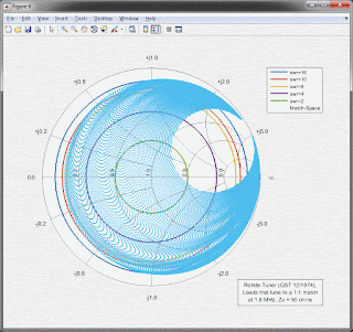
I initially wrote the MATLAB script to plot an outline on a Smith Chart that would enclose the range of impedances that could be matched to 1:1 at a selected frequency. Here's an example of how that plot looked:
But I wasn't happy with the "visibility" of the outline, and so I changed the script to show the encompassed area a bit more dramatically by filling it in, like this:
I hope you agree that this second plot is much easier to see.
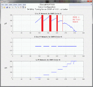
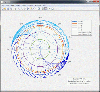
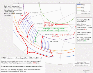
As for the MATLAB script itself, all it's really doing is stepping the values of the network's two variable components (step size selected by me) over the range of all of their possible values. A 50 ohm load is connected to the network's input and the program calculates the impedance that this 50 ohms is transformed to be when looking into the network's output terminals. This transformed-impedance is calculated at every step of the component values, and it is the complex-conjugate of a load impedance that, when connected to the network's output terminals, would be transformed to 50 ohms at the network's input with those same settings of the variable component values.
The Nye Viking MB-V-A Antenna Tuner
Let's start off with the Nye Viking MB-V-A. (Note: this tuner was reviewed in the June, 1994 issue of QST).
The Nye Viking MB-V-A tuner is, essentially, an L-Network (series-L, shunt-C), although the 2:1 auto-transformer at the output (which provides a 4:1 impedance transformation) and the 230 pF fixed capacitor at its input might throw you off.
But first, a quick note about the MATLAB routine used to create the plots below...
I thought it would be fun to use my recently-purchased copy of MATLAB to create a MATLAB script to let me do a bit of analysis of tuner design -- but rather than analyze power loss (as I'd done in other posts on this blog), I thought I'd look into the "range" of load impedances that a tuner could match to a 1:1 SWR at 50 ohms.
I initially wrote the MATLAB script to plot an outline on a Smith Chart that would enclose the range of impedances that could be matched to 1:1 at a selected frequency. Here's an example of how that plot looked:
(click on image to enlarge)
But I wasn't happy with the "visibility" of the outline, and so I changed the script to show the encompassed area a bit more dramatically by filling it in, like this:
I hope you agree that this second plot is much easier to see.
As for the MATLAB script itself, all it's really doing is stepping the values of the network's two variable components (step size selected by me) over the range of all of their possible values. A 50 ohm load is connected to the network's input and the program calculates the impedance that this 50 ohms is transformed to be when looking into the network's output terminals. This transformed-impedance is calculated at every step of the component values, and it is the complex-conjugate of a load impedance that, when connected to the network's output terminals, would be transformed to 50 ohms at the network's input with those same settings of the variable component values.
The Nye Viking MB-V-A Antenna Tuner
Let's start off with the Nye Viking MB-V-A. (Note: this tuner was reviewed in the June, 1994 issue of QST).
The Nye Viking MB-V-A tuner is, essentially, an L-Network (series-L, shunt-C), although the 2:1 auto-transformer at the output (which provides a 4:1 impedance transformation) and the 230 pF fixed capacitor at its input might throw you off.
The 2:1 impedance transformer consists of 2 windings of a 3-winding (trifilar wound) transformer, and this configuration is used when either the "Coax A" or 'Coax B" output is selected. There is no transformer in-circuit if the "Single Wire" output is selected, and if "Twin Lead" is selected, all three windings of the transformer are used and this transformer becomes (I believe) a 1:1 voltage balun.
The 2:1 transformer essentially multiplies the load impedance seen by the tuner by four, thus increasing the range of impedances that can be matched (because the series-shunt L-network is good at matching impedances whose resistive component is greater than 50 ohms). E.g. 15 ohms would first be multiplied up to 60 ohms prior to being matched by the network.
Let's take a look at the impedances that can be matched by this tuner. Here's the range of loads that are matchable to a 1:1 SWR at 1.8 MHz:
Note the lack of coverage over a significant area of the Smith Chart at 1.8 MHz.
Coverage improves at 3.5 MHz:
The range of loads that are matchable to a 1:1 SWR at 7 MHz:
The range of loads that are matchable to a 1:1 SWR at 14 MHz:
The range of loads that are matchable to a 1:1 SWR at 30 MHz:
And here's the MATLAB code I used to calculate the impedances that the Nye Viking tuner can match to 1:1:
Antenna Coupler, Ulrich L. Rohde, DJ2LR/W2, (QST, December, 1974)
This antenna tuner is also a variant of an L-Network (series-L, shunt-C). It appeared in an article titled "Some Ideas on Antenna Couplers," by Ulrich L. Rhode, DJ2LR/W2, in QST, December, 1974. (And if my memory serves me correctly, I also saw the design published in the September 13, 1975 issue of Electronic Design).
Like the Nye Viking MB-V-A, it also contains a 2:1 auto-transformer (providing a 4:1 impedance transformation). But this design has the auto-transformer at the input of the network, not at the output.
The 2:1 auto-transformer at the network input is essentially multiplying up the impedance it sees by a factor of 4:1. In other words, the goal of the network is now to transform the load impedance to 12.5 ohms, rather than to 50 ohms. The transformer then kicks the 12.5 ohms up to 50 ohms, thus presenting the appropriate load to the transmitter.
The tuning network itself is a series-shunt lowpass L-network, formed by the adjustable 28 uH inductor and 1350 pF capacitor. Per the QST article, the 1 uH fixed across the auto-transformer's "secondary" allows matching loads whose resistive component is less than 12.5 ohms. And the 500 pF series capacitor is to improve the matching range on 160 meters, where the variable shunt capacitor would normally have to be quite large (e.g. 4000 pF, per the article) to match a 50 ohm load. The series cap at the network's output effectively "transforms" an impedance (e.g. 50 ohms) to a higher impedance that can be matched more easily with the 1350 pF variable cap. (Think of the 500 pF series cap in combination with the 1350 pF variable shunt capacitor as forming a "shunt-series" L-network that transforms a low impedance to a high one).
Let's look at some of the bands where the network component values might have their largest impact on coverage of impedances.
First, let's look at the range of loads that are matchable to a 1:1 SWR at 1.8 MHz:
The range of loads that are matchable to a 1:1 SWR at 7 MHz:
The range of loads that are matchable to a 1:1 SWR at 14 MHz:
The range of loads that are matchable to a 1:1 SWR at 30 MHz:
Here's the MATLAB routine used for the Rohde coupler calculations:
The 2:1 transformer essentially multiplies the load impedance seen by the tuner by four, thus increasing the range of impedances that can be matched (because the series-shunt L-network is good at matching impedances whose resistive component is greater than 50 ohms). E.g. 15 ohms would first be multiplied up to 60 ohms prior to being matched by the network.
Let's take a look at the impedances that can be matched by this tuner. Here's the range of loads that are matchable to a 1:1 SWR at 1.8 MHz:
(click on image to enlarge)
Note the lack of coverage over a significant area of the Smith Chart at 1.8 MHz.
Coverage improves at 3.5 MHz:
(click on image to enlarge)
The range of loads that are matchable to a 1:1 SWR at 7 MHz:
(click on image to enlarge)
The range of loads that are matchable to a 1:1 SWR at 14 MHz:
(click on image to enlarge)
The range of loads that are matchable to a 1:1 SWR at 30 MHz:
(click on image to enlarge)
And here's the MATLAB code I used to calculate the impedances that the Nye Viking tuner can match to 1:1:
(click on image to enlarge)
Antenna Coupler, Ulrich L. Rohde, DJ2LR/W2, (QST, December, 1974)
This antenna tuner is also a variant of an L-Network (series-L, shunt-C). It appeared in an article titled "Some Ideas on Antenna Couplers," by Ulrich L. Rhode, DJ2LR/W2, in QST, December, 1974. (And if my memory serves me correctly, I also saw the design published in the September 13, 1975 issue of Electronic Design).
Like the Nye Viking MB-V-A, it also contains a 2:1 auto-transformer (providing a 4:1 impedance transformation). But this design has the auto-transformer at the input of the network, not at the output.
The 2:1 auto-transformer at the network input is essentially multiplying up the impedance it sees by a factor of 4:1. In other words, the goal of the network is now to transform the load impedance to 12.5 ohms, rather than to 50 ohms. The transformer then kicks the 12.5 ohms up to 50 ohms, thus presenting the appropriate load to the transmitter.
The tuning network itself is a series-shunt lowpass L-network, formed by the adjustable 28 uH inductor and 1350 pF capacitor. Per the QST article, the 1 uH fixed across the auto-transformer's "secondary" allows matching loads whose resistive component is less than 12.5 ohms. And the 500 pF series capacitor is to improve the matching range on 160 meters, where the variable shunt capacitor would normally have to be quite large (e.g. 4000 pF, per the article) to match a 50 ohm load. The series cap at the network's output effectively "transforms" an impedance (e.g. 50 ohms) to a higher impedance that can be matched more easily with the 1350 pF variable cap. (Think of the 500 pF series cap in combination with the 1350 pF variable shunt capacitor as forming a "shunt-series" L-network that transforms a low impedance to a high one).
Let's look at some of the bands where the network component values might have their largest impact on coverage of impedances.
First, let's look at the range of loads that are matchable to a 1:1 SWR at 1.8 MHz:
(click on image to enlarge)
The range of loads that are matchable to a 1:1 SWR at 3.5 MHz:
(click on image to enlarge)
(click on image to enlarge)
(click on image to enlarge)
Here's the MATLAB routine used for the Rohde coupler calculations:
(click on image to enlarge)
Comparing the two tuners, it seems to me that the Nye-Viking model has a wider match range than the Rohde design on the higher bands, and is comparable to the Rohde tuner on the lower bands (although the Rohde design might be better on 160 meters).
The following note was received from Ulrich Rohde, N1UL, on 19 March 2021, and it adds additional insight into his design:
Good evening,
The problem with transformer equivalent circuits is, they only behave
correctly for real values not imaginary ( complex) values.
My antenna tuner guarantees a correct but low real / resistive value to
be transformed to 50 Ohm.
A better way on my part would have been to have a selection also for
through (50 to 50) Ohm or a transformation from 200 ohm res to 50
ohm.
The end fed antennas are not connected an half wavelength and the
mismatch causes losses and dissipation in the ferrite core.
The most universal tuner is still the version where the binary capacitors
can be switch at the antenna site or the 50 TX side.
Having the transformer as a third variable element just complicates
things. If you have a capacitance meter and 100 pf capacitor connect it to
4 :1 transformer and at the 4:1 output don’t be disappointed if it
doesn’t read 400 pF at the low impedance side...
Also please remember my tuner was mainly designed to match Manpack
antennas of less then 3 m and yes occasionally wire antennas with less
then 10 m length ...
When skiing in the Swiss alps in 1968 I used my 20 W Manpack on 80
and 40 to stay in touch with Germany and other countries !
Thanks, you do very good work.
73 de Ulrich, N1UL
He adds in a later email...A perfect match does not mean perfect radiation. Antenna length of 1/8 of a wavelength can be matched but the low radiation resistance can reduce the efficiency below 1 % , not very useful.
Thanks, Ulrich, N1UL
Antenna Tuner Blog Posts:
A quick tutorial on Smith Chart basics:
http://k6jca.blogspot.com/2015/03/a-brief-tutorial-on-smith-charts.html
Plotting Smith Chart Data in 3-D:
http://k6jca.blogspot.com/2018/09/plotting-3-d-smith-charts-with-matlab.html
The L-network:
http://k6jca.blogspot.com/2015/03/notes-on-antenna-tuners-l-network-and.html
A correction to the usual L-network design constraints:
http://k6jca.blogspot.com/2015/04/revisiting-l-network-equations-and.html
Calculating L-Network values when the components are lossy:
http://k6jca.blogspot.com/2018/09/l-networks-new-equations-for-better.html
A look at highpass T-Networks:
http://k6jca.blogspot.com/2015/04/notes-on-antenna-tuners-t-network-part-1.html
More on the W8ZR EZ-Tuner:
http://k6jca.blogspot.com/2015/05/notes-on-antenna-tuners-more-on-w8zr-ez.html (Note that this tuner is also discussed in the highpass T-Network post).
The Elecraft KAT-500:
http://k6jca.blogspot.com/2015/05/notes-on-antenna-tuners-elecraft-kat500.html
The Nye Viking MB-V-A tuner and the Rohde Coupler:
http://k6jca.blogspot.com/2015/05/notes-on-antenna-tuners-nye-viking-mb-v.html
The Drake MN-4 Tuner:
http://k6jca.blogspot.com/2018/08/notes-on-antenna-tuners-drake-mn-4.html
Measuring a Tuner's "Match-Space":
Standard Caveat:
I could easily have made a mistake in my MATLAB program or in my post above. If anything looks wrong, or if you'd like clarification, please feel free to contact me!
And if you'd like me to apply this MATLAB script to other networks, please feel free to contact me.
A quick tutorial on Smith Chart basics:
http://k6jca.blogspot.com/2015/03/a-brief-tutorial-on-smith-charts.html
Plotting Smith Chart Data in 3-D:
http://k6jca.blogspot.com/2018/09/plotting-3-d-smith-charts-with-matlab.html
The L-network:
http://k6jca.blogspot.com/2015/03/notes-on-antenna-tuners-l-network-and.html
A correction to the usual L-network design constraints:
http://k6jca.blogspot.com/2015/04/revisiting-l-network-equations-and.html
Calculating L-Network values when the components are lossy:
http://k6jca.blogspot.com/2018/09/l-networks-new-equations-for-better.html
A look at highpass T-Networks:
http://k6jca.blogspot.com/2015/04/notes-on-antenna-tuners-t-network-part-1.html
More on the W8ZR EZ-Tuner:
http://k6jca.blogspot.com/2015/05/notes-on-antenna-tuners-more-on-w8zr-ez.html (Note that this tuner is also discussed in the highpass T-Network post).
The Elecraft KAT-500:
http://k6jca.blogspot.com/2015/05/notes-on-antenna-tuners-elecraft-kat500.html
The Nye Viking MB-V-A tuner and the Rohde Coupler:
http://k6jca.blogspot.com/2015/05/notes-on-antenna-tuners-nye-viking-mb-v.html
http://k6jca.blogspot.com/2018/08/notes-on-antenna-tuners-drake-mn-4.html
Measuring a Tuner's "Match-Space":
Measuring Tuner Power Loss:
Standard Caveat:
I could easily have made a mistake in my MATLAB program or in my post above. If anything looks wrong, or if you'd like clarification, please feel free to contact me!
And if you'd like me to apply this MATLAB script to other networks, please feel free to contact me.


