Kai Siwiak, KE4PT, forwarded to me his analysis of the Icom AH-4 Remote Tuner. With his permission I have added it to this blog.
I analyzed the Icom AH-4 tuner using the circuit of Figure 1.

Tuner Analysis:
I terminated the “Radio side” of the tuner with a "perfect" 50 ohm resistor and used MathCAD to calculate the impedances on the “Antenna side” while stepping through the allowed component values (both L and C) for two cases (0 – 2400 pF capacitor bank on the output, then on the input), and across ham bands from 1.8 to 54 MHz.I then plotted on a Smith chart the complex conjugate of the calculated impedances on the “Antenna side”. This maps the impedances that the AH-4 can match, given the range of component values in Figure 1. Figure 2 shows the range of impedances the AH-4 can match plotted on a Smith chart.

Notice how the coverage on the Smith chart gets whittled away as the frequency decreases. It indicates that the component values do not have sufficient range to cover the whole chart at those frequencies!
Impedance coverage is not continuous, but depends on the step size of the components, and that granularity is revealed here by the inductor and capacitor steps in Figure 1.
What this implies is that the tuner range of matching can be completely specified by:
(1) the tuner topology, here in Figure 1, a reversible L network with additional switched capacitance on the antenna side;
(2) the range of component values and the component step size; usually the minimum value of the inductor and minimum value of the capacitor in the capacitor bank.
Also what is not revealed here is the tuning algorithm and tuning strategy. These are typically proprietary features. Given estimates of the inductor Q it would be possible to calculate the tuner losses across the Smith chart at various frequencies. The AH-4 inductors are air-wound, so will be lower loss than ferrite inductors.
On tuning strategy, the AH-4 initially sets the connected compatible radio RF power to 10 W, and switches in a 10 dB attenuator between the radio and the tuner. Thus no more than 1 W is every supplied to the antenna during tuning, and the radio transmitter always “sees” more than 20 dB return loss (SWR < 1.2:1) during the tuning process, ensuring a valid tuning solution.
I have similarly analyzed the Elecraft T1 miniature ATU, which also uses a reversible L network with 0 to 1300 pF by 10 pF and 0 to 7.5 uH by 0.055 uH (32,768 combinations). Its range of component values is smaller than that of the AH-4, so it cover less of the Smith chart. Its inductors are not air core, so losses will be higher than with the AH-4.
Kindest regards,
Kai Siwiak, KE4PT
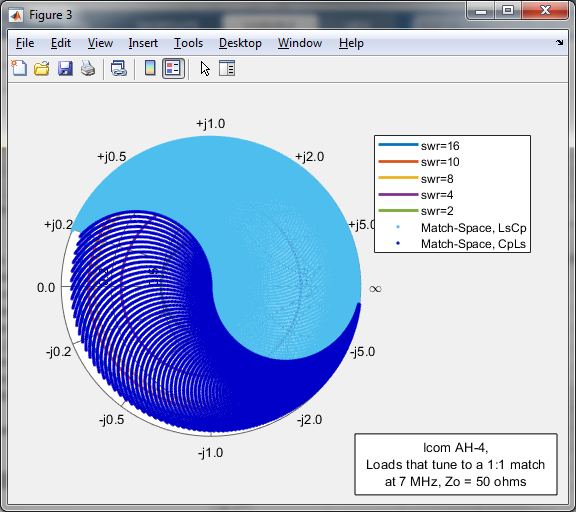
Some Additional Notes (by Jeff, K6JCA)
To verify Kai's calculations, I analyzed the AH-4 using a MATLAB script I had written for analyzing tuners (e.g. the KAT-500). If you compare my plotted results, below, with Kai's Figure 2, you will see that they match quite well.


Antenna Tuner Blog Posts:
A quick tutorial on Smith Chart basics:
http://k6jca.blogspot.com/2015/03/a-brief-tutorial-on-smith-charts.html
Plotting Smith Chart Data in 3-D:
http://k6jca.blogspot.com/2018/09/plotting-3-d-smith-charts-with-matlab.html
The L-network:
http://k6jca.blogspot.com/2015/03/notes-on-antenna-tuners-l-network-and.html
A correction to the usual L-network design constraints:
http://k6jca.blogspot.com/2015/04/revisiting-l-network-equations-and.html
Calculating L-Network values when the components
are lossy:
http://k6jca.blogspot.com/2018/09/l-networks-new-equations-for-better.html
A look at highpass T-Networks:
http://k6jca.blogspot.com/2015/04/notes-on-antenna-tuners-t-network-part-1.html
More on the W8ZR EZ-Tuner:
http://k6jca.blogspot.com/2015/05/notes-on-antenna-tuners-more-on-w8zr-ez.html (Note that this tuner is also discussed in the highpass T-Network
post).
The Elecraft KAT-500:
http://k6jca.blogspot.com/2015/05/notes-on-antenna-tuners-elecraft-kat500.html
The Nye Viking MB-V-A tuner and the Rohde Coupler:
http://k6jca.blogspot.com/2015/05/notes-on-antenna-tuners-nye-viking-mb-v.html
The Drake MN-4 Tuner:
http://k6jca.blogspot.com/2018/08/notes-on-antenna-tuners-drake-mn-4.html
The Icom AH-4 Tuner:
http://k6jca.blogspot.com/2021/03/notes-on-antenna-tuners-icom-ah-4-by.html
Measuring a Tuner's "Match-Space":
http://k6jca.blogspot.com/2018/08/notes-on-antenna-tuners-determining.html
Measuring Tuner Power Loss:
http://k6jca.blogspot.com/2018/08/additional-notes-on-measuring-antenna.html
Standard Caveat:
Also, I will note:
This design and any associated information is distributed in the hope that it will be useful, but WITHOUT ANY WARRANTY; without even the implied warranty of MERCHANTABILITY or FITNESS FOR A PARTICULAR PURPOSE.


No comments:
Post a Comment