In my previous post (here) I described the method of determining a transmission line's Characteristic Impedance Zo from measurements of its input impedance when terminated with a short and when terminated with an open.
In this new post I will describe a second method that is sometimes used determine a transmission line's Zo (such as in some versions of the NanoVNA's firmware). I will call this second method the "1/8th-Lambda Method" (where "Lambda" is the wavelength of the signal on the transmission line). I first learned of this method here.
The 1/8th-Lambda method uses S11 measurements of a transmission line, and these can be made with the line terminated either with an OPEN or with a SHORT.
Assuming the transmission line is terminated with an OPEN, the principle behind this technique is that the magnitude of the reactive-component 'Xin' of Zin, the terminated transmission line's input impedance (as calculated from S11), will equal Zo at a point 1/8th of a wavelength from the point at S11's phase passes through 180 degrees (or 0 degrees, if the transmission line is terminated with a SHORT).
To find this 1/8th-Lambda point, assuming the line is terminated with an OPEN and the S11 frequency sweep is starting near 0 Hz:
1. Find the frequency at which the phase of S11 is -180 degrees (on the left-hand side of the Smith Chart and on the x-axis). This is the quarter-wavelength frequency of an OPEN-terminated transmission line.
2. Divide this frequency by 2. This new frequency is the eighth-wavelength frequency of the transmission line. Note S11 at this point.
3. Convert this S11 value to Zin (where Zin = Rin + jXin). The value of Xin will be the negative of Zo, and therefore Zo = -Xin.
This same method can be used, with a few small changes, if the transmission line is terminated with a SHORT:
1. Find the frequency at which the phase of S11 is 0 degrees on the right-hand side of the Smith Chart. This is the quarter-wavelength frequency for this length of transmission line (assuming the S11 scan starts near 0 Hz).
2. Divide this frequency by 2. This new frequency is the frequency for which the transmission line is an eighth of a wavelength long. Note S11 at this point.
3. Convert this S11 value to Zin (Zin = Rin + jXin). The value of Xin will be the negative of Zo, and therefore Zo = -Xin.
The 1/8-Lambda Method and Lossless Transmission Lines:
Let's look at the principle behind this technique assuming a lossless transmission line...
I've used SimSmith to model 40 feet of ideal (lossless) 75-ohm coax terminated with an OPEN. The simulation parameters are in the image, below.
With this simulation I created an S11 file (frequency spanning from 1 KHz to 6.001 MHz.). The S11 plot is shown below.
Note that S11, the Reflection-Coefficient, curve passes through -180 degrees at about 4.057 MHz. At this frequency the transmission-line is a quarter-wavelength long.
To find the eighth-wavelength point, we divide 4.057 MHz by 2, which results in a frequency of 2.0285 MHz.
Convert the measured S11 data for this frequency to Zin: assuming the VNA is calibrated for 50 ohms, Zin = 50*(1+S11)/(1-S11).
At this point on the Smith Chart, above, (actually, close to it -- the S11 capture skips 2.0285 MHz), Zin = -4e-8 - j75.04 ohms
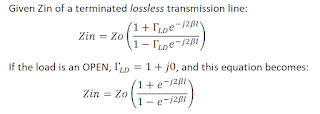
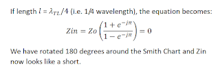
From the derivation above for an OPEN termination, Zin = -jZo, therefore Zo = jZin.
Substituting in the value of Zin and solving...
Zo = j*(-4e-8-j75.04) = 75.04 - j(-4e-8).
The imaginary term is negligible. Therefore:
Zo = 75.04 ohms.
Example: Lossless Transmission Line Terminated with a SHORT:
We can do a similar calculation if the transmission line is terminated with a SHORT. Below is the Smith Chart showing the Reflection Coefficient path.
From the derivation above for a SHORT termination, Zin = jZo, therefore Zo = -jZin.
Substituting in the value of Zin and solving...
Zo = -j*(-4e-8 + j74.96) = 74.96 + j(4e-8).
The imaginary term is again negligible, and thus:
Zo = 74.96 ohms.
Conclusion: For a lossless transmission line (or one whose loss is insignificant) the 1/8-Lambda method works quite well at finding Zo of the transmission line.
How well does this technique perform if the line is lossy?
For a lossless transmission line, Zo is a real value and equal to the SQRT(L/C). But for a lossy transmission line Zo is a complex value whose real and imaginary parts are both frequency dependent, as shown in the following two slides:
Below is the plot of S11 for 40 feet of Belden 8241 coax terminated with an OPEN. Note that as frequency increases the Reflection Coefficient is spiraling in from the Smith Chart's unit-circle boundary.
In the plot below I have applied the 1/8-Lambda technique to two different S11 simulated-measurements. In one measurement the 40 feet of Belden 8241 coax was terminated with an OPEN, and in the other it was terminated with a SHORT.
Using the same procedure that I used for the lossless line, the 1/8th-Lambda points are at 1.999 MHz (although there is some question as to this frequency -- more on this in a bit...).
Converting the S11 values at 1.999MHz to Zin, let's use the equations derived earlier (for a lossless line) to find Zo:
From the Smith Chart above, Zin at the 1/8th-Lambda points for the SHORT and the OPEN are:.
- For the OPEN termination, Zin @ (1.999 MHz) = 1.721 - j75.98 ohms
- For the SHORT termination, Zin @ (1.999 MHz) = 7.595 + j75.56 ohms.
1. The 1/8th-Lambda method assumes that the quarter-wavelength frequency is when the angle of S11 is -180 degrees (for an OPEN termination). But for a lossy line, the quarter-wavelength point is not where S11's phase is -180 degrees. Zo is a complex number for lossy lines, and thus Zin at 1/4 wavelength would also have some amount of reactance, meaning that S11, at 1/4 Lambda, will have an angle other than 180 or 0 degrees. How much of a difference would this make? I don't know.
2. The 1/8th-Lambda method assumes that the frequency for the 1/8th wavelength is half the frequency of the quarter-wavelength. But the velocity factor of lossy transmission lines is not a constant, but varies with frequency (see here and here).
Therefore, a quarter-wavelength length of transmission line at one frequency will not be an eighth-wavelength at half that frequency. How much difference does this make? I don't know.
3. Note that the imaginary component Xo (the reactance of the calculated Zo) is negative if the SHORT termination is used and positive if the OPEN termination is used. This sign convention will always be the case, irrespective of Zo, as long as the line is lossy, because Rin is always positive, but it is multiplied by +j to calculate Zo for an OPEN termination and by -j to calculate Zo for a SHORT termination (see the Zin to Zo conversion equations for 1/8th-Lambda earlier in this post).
Thus, the sign of Xo (the reactance of Zo) depends upon the load being an open or a short, which makes this value questionable.
4. If we increase frequency to a point where loss is small, do the results from the 1/8th-Lambda technique improve?
Below is an S11 plot of 40 feet of Belden 8241 75-ohm coax out to 100 MHz.
Note that the frequency where S11 crosses 0 degrees is about 88.901 MHz, and the frequency where S11 crosses 180 degrees is about 92.951 degrees. The frequency half-way between these two frequencies is the 1/8th-lambda frequency, which, in this case, is 90.926 Mhz.
At this point S11 represents an input impedance, Zin, of 21.51-j72.29 ohms.
Given that the line is terminated with an OPEN, we use the following formula to convert Zin to Zo at the 1/8th-Lambda frequency:
Zo = -Xin + jRin = 72.29 + j21.51 ohms.
However, using the equation Zo = SQRT(Zsc*Zoc) at this frequency, Zo, per the plots below, calculates to be:
Zo = 75.3 - j0.29 ohms
So there seems to an error at high frequencies, too.
Lossy-Line Equations:
In addition to the uncertainty in the quarter-wave frequency and in the Velocity Factor, part of the problem is undoubtedly due to the equations derived for a lossless transmission line are a simplification of the equations for a lossy line.
Let's derive those equations...
Given the last equation, above, if α is known, then the equation for Zo can be modified. But α for the lossy line would first need to be found. Plus, there are still the unresolved issues of Zo being complex (and its angle at 1/4 Lambda, hence uncertainty in the quarter-wave frequency) as well as frequency-dependent Velocity Factor.
In other words, the one-eighth-Lambda technique might get you close to the actual Zo, but there will be some amount of error in the calculated value.
Conclusions:
1. If the transmission line is lossy, expect some amount of error in your Zo calculation. But you will probably be reasonably close to the transmission line's actual Zo.
Other Notes:
Owen Duffy has an interesting post on an alternate method for finding the 1/8th-Lambda frequency and its associated Zo. See here.
Essentially, he measures the impedances of both a shorted line and an open line, and then, at the frequency where the |X| values of the two measurements intersect, he identifies this frequency as the 1/8th-Lambda point and defines Zo to be equal to |X| at this frequency.
Resources:
Transmission Line stuff: https://122.physics.ucdavis.edu/sites/default/files/files/Electronics/TransmissionLinesPart_II.pdf
On frequency-dependent Velocity Factor: https://scholar.valpo.edu/cgi/viewcontent.cgi?filename=28&article=1000&context=engineering_oer&type=additional
and here: https://owenduffy.net/transmissionline/concept/mvf/index.htm
Standard Caveat:
As always, I might have made a mistake in my equations, assumptions,
drawings, or interpretations. If you see anything you believe to be in
error or if anything is confusing, please feel free to contact me or comment
below.
And so I should add -- this information is distributed in
the hope that it will be useful, but WITHOUT ANY WARRANTY; without even the
implied warranty of MERCHANTABILITY or FITNESS FOR A PARTICULAR PURPOSE.


No comments:
Post a Comment